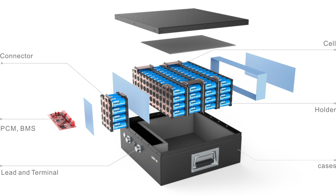
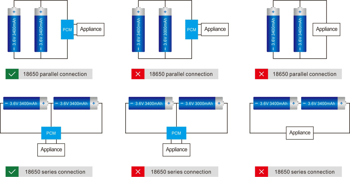
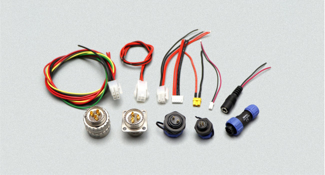
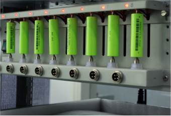
How-to-Store-Batteries(Cover)

Learn about storage temperatures and state-of-charge conditions.

The recommended storage temperature for most batteries is 15°C (59°F); the extreme allowable temperature is –40°C to 50°C (–40°C to 122°F) for most chemistries.

Lead acid

You can store a sealed lead acid battery for up to 2 years. Since all batteries gradually self-discharge over time, it is important to check the voltage and/or specific gravity, and then apply a charge when the battery falls to 70 percent state-of-charge, which reflects 2.07V/cell open circuit or 12.42V for a 12V pack. (The specific gravity at 70 percent charge is roughly 1.218.) Lead acid batteries may have different readings, and it is best to check the manufacturer’s instruction manual. Some battery manufacturer may further let a lead acid to drop to 60 percent before recharge. See BU-903: How to Measure State-of-charge.)

Low charge induces sulfation, an oxidation layer on the negative plate that inhibits current flow. Topping charge and/or cycling may restore some of the capacity losses in the early stages of sulfation. (See BU-804b: Sulfation and How to Prevent it.)

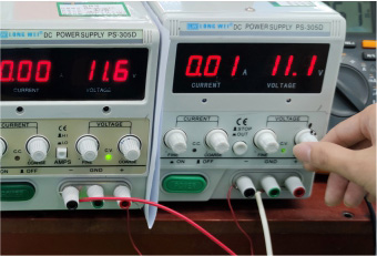
Sulfation may prevent charging small sealed lead acid cells, such as the Cyclone by Hawker, after prolonged storage. These batteries can often be reactivated by applying an elevated voltage. At first, the cell voltage under charge may go up to 5V and draw very little current. Within 2 hours or so, the charging current converts the large sulfate crystals into active material, the cell resistance drops and the charge voltage gradually normalizes. At between 2.10V and 2.40V the cell is able to accept a normal charge. To prevent damage, set the current limit to a very low level. Do not attempt to perform this service if the power supply does not have current limiting. (See BU-405: Charging with a Power Supply.)

Nickel-based

Recommended storage is around 40 percent state-of-charge (SoC). This minimizes age-related capacity loss while keeping the battery operational and allowing for some self-discharge. Nickel-based batteries can be stored in a fully discharged state with no apparent side effect.

Measuring SoC by voltage is difficult on nickel-based batteries. A flat discharge curve, agitation after charge and discharge and temperature affects the voltage. The good news is that the charge level for storage is not critical for this chemistry, so simply apply some charge if the battery is empty and store it in a cool and dry place. With some charge, priming should be quicker than if stored in a totally discharged state.

Nickel-metal-hydride can be stored for 3–5 years. The capacity drop that occurs during storage is partially reversible with priming. Nickel-cadmium stores well. The US Air Force was able to deploy NiCd batteries that had been in storage for 5 years with good recovered capacities after priming. It is believed that priming becomes necessary if the voltage drops below 1V/cell. Primary alkaline and lithium batteries can be stored for up to 10 years with only moderate capacity loss.

Lithium-based

There is virtually no self-discharge below about 4.0V at 20C (68F); storing at 3.7V yields amazing longevity for most Li-ion systems. Finding the exact 40–50 percent SoC level to store Li-ion is not that important. At 40 percent charge, most Li-ion has an OCV of 3.82V/cell at room temperature. To get the correct reading after a charge or discharge, rest the battery for 90 minutes before taking the reading. If this is not practical, overshoot the discharge voltage by 50mV or go 50mV higher on charge. This means discharging to 3.77V/cell or charging to 3.87V/cell at a C-rate of 1C or less. The rubber band effect will settle the voltage at roughly 3.82V. Figure 1 shows the typical discharge voltage of a Li-ion battery.

Discharge OCV

Figure 1: Discharge voltage as a function of state-of-chargeBattery SoC is reflected in OCV. Lithium manganese oxide reads 3.82V at 40% SoC (25°C), and about 3.70V at 30% (shipping requirement). Temperature and previous charge and discharge activities affect the reading. Allow the battery to rest for 90 minutes before taking the reading.

Li-ion cannot dip below 2V/cell for any length of time. Copper shunts form inside the cells that can lead to elevated self-discharge or a partial electrical short. (See BU-802b: Elevated Self-discharge.) If recharged, the cells might become unstable, causing excessive heat or showing other anomalies. Li-ion batteries that have been under stress may function normally but are more sensitive to mechanical abuse. Liability for incorrect handling should go to the user and not the battery manufacturer.

Alkaline

Alkaline and other primary batteries are easy to store. For best results, keep the cells at cool room temperature and at a relative humidity of about 50 percent. Do not freeze alkaline cells, or any battery, as this may change the molecular structure. Some lithium-based primary batteries need special care that is described in BU-106a: Choices of Primary Batteries.

Capacity Loss during Storage

Storage induces two forms of losses: Self-discharge that can be refilled with charging before use, and non-recoverable losses that permanently lower the capacity. Table 2 illustrates the remaining capacities of lithium- and nickel-based batteries after one year of storage at various temperatures. Li-ion has higher losses if stored fully charged rather than at a SoC of 40 percent. (See BU-808: How to Prolong Lithium-based Batteries to study capacity loss in Li-ion.)

Temperature

Lead acid

at full charge

Nickel-based

at any charge

Lithium-ion (Li-cobalt)

40% charge

100% charge

0°C

25°C

40°C

60°C

97%

90%

62%

38%
(after 6 months)

99%

97%

95%

70%

98%

96%

85%

75%

94%

80%

65%

60%
(after 3 months)

Table 2: Estimated recoverable capacity when storing a battery for one year. Elevated temperature hastens permanent capacity loss. Depending on battery type, lithium-ion is also sensitive to charge levels.

Batteries are often exposed to unfavorable temperatures, and leaving a mobile phone or camera on the dashboard of a car or in the hot sun are such examples. Laptops get warm when in use and this increases the battery temperature. Sitting at full charge while plugged into the mains shortens battery life. Elevated temperature also stresses lead- and nickel-based batteries. (See BU-808: How to Prolong Lithium-based Batteries.)

Nickel-metal-hydride can be stored for 3–5 years. The capacity drop that occurs during storage is partially reversible with priming. Nickel-cadmium stores well. The US Air Force was able to deploy NiCd batteries that had been in storage for 5 years with good recovered capacities after priming. It is believed that priming becomes necessary if the voltage drops below 1V/cell. Primary alkaline and lithium batteries can be stored for up to 10 years with only moderate capacity loss.

You can store a sealed lead acid battery for up to 2 years. Since all batteries gradually self-discharge over time, it is important to check the voltage and/or specific gravity, and then apply a charge when the battery falls to 70 percent state-of-charge, which reflects 2.07V/cell open circuit or 12.42V for a 12V pack. (The specific gravity at 70 percent charge is roughly 1.218.) Lead acid batteries may have different readings, and it is best to check the manufacturer’s instruction manual. Some battery manufacturer may further let a lead acid to drop to 60 percent before recharge. Low charge induces sulfation, an oxidation layer on the negative plate that inhibits current flow. Topping charge and/or cycling may restore some of the capacity losses in the early stages of sulfation. (See BU-804b: Sulfation and How to Prevent it.)

Sulfation may prevent charging small sealed lead acid cells, such as the Cyclone by Hawker, after prolonged storage. These batteries can often be reactivated by applying an elevated voltage. At first, the cell voltage under charge may go up to 5V and draw very little current. Within 2 hours or so, the charging current converts the large sulfate crystals into active material, the cell resistance drops and the charge voltage gradually normalizes. At between 2.10V and 2.40V the cell is able to accept a normal charge. To prevent damage, set the current limit to a very low level. Do not attempt to perform this service if the power supply does not have current limiting. (See BU-405: Charging with a Power Supply.)

Alkaline batteries are easy to store. For best results, keep the cells at cool room temperature and at a relative humidity of about 50 percent. Do not freeze alkaline cells, or any battery, as this may change the molecular structure.

AirShip

Li-ion batteries not only live longer when stored partially charged; they are also less volatile in shipment should an anomaly occur. The International Air Transport Association (IATA) and FAA mandate that all removable Li-ion packs be shipped at 30% state-of-charge. (More on BU-704a: Shipping Lithium-based Batteries by Air.) SoC can be estimated by measuring the open circuit voltage of a rested battery. (See also BU-903: How to Measure State-of-charge.)

Relating SoC to voltage can be inaccurate as the voltage curve of Li-ion between 20% to 100% charge is flat, as Figure 1 demonstrates. Temperature also plays a role, so do the active materials used in a cell. Aviation authorities seem less concerned about the exact 30% SoC but the importance of shipping Li-ion below 50% SoC. Larger misgivings are wrong labeling by passing Li-ion as a benign nickel-based chemistry.

To bring Li-ion to 30% SoC, discharge the battery in a device featuring a fuel gauge and terminate the discharge at 30% charge. The Embedded Battery Management System (BMS) does a reasonably good job giving SoC information but the measurements are seldom accurate. A full discharge to “Low Batt” is acceptable as long as the battery receives a charge at destination. Keeping Li-ion in a discharged state for a few months could slip the pack to sleep mode. (See BU-808a: How to Awaken a Sleeping Li-ion.)

Modern chargers feature the “AirShip” program that prepares a Li-ion pack for air shipment by discharging or charging the battery to 30% SoC on command. Typical methods are a full discharge with subsequent recharge to 30% using coulomb counting or advanced Kalman filters. Li-ion batteries built into devices have less stringent SoC requirements than removable packs.

Simple Guidelines for Storing Batteries

  • Primary batteries store well. Alkaline and primary lithium batteries can be stored for 10 years with moderate loss capacity.
  • When storing, remove the battery from the equipment and place in a dry and cool place.
  • Avoid freezing. Batteries freeze more easily if kept in discharged state.
  • Charge lead acid before storing and monitor the voltage or specific gravity frequently; apply a charge if below 2.07V/cell or if SG is below 1.225 (most starter batteries).
  • Nickel-based batteries can be stored for 3–5years, even at zero voltage; prime before use.
  • Lithium-ion must be stored in a charged state, ideally at 40 percent. This prevents the battery from dropping below 2.50V/cell, triggering sleep mode.
  • Discard Li-ion if kept below 2.00/V/cell for more than a week. Also discard if the voltage does not recover normally after storage. (See BU-802b: What does Elevated Self-discharge do?)
CAUTION
When charging an SLA with over-voltage, current limiting must be applied to protect the battery. Always set the current limit to the lowest practical setting and observe the battery voltage and temperature during charge. In case of rupture, leaking electrolyte or any other cause of exposure to the electrolyte, flush with water immediately. If eye exposure occurs, flush with water for 15 minutes and consult a physician immediately.

Wear approved gloves when touching electrolyte, lead and cadmium. On exposure to skin, flush with water immediately.

Gel Lead Acid Battery(Demo picture)

Learn the unique advantages of lead acid batteries

The early gelled lead acid battery developed in the 1950s by Sonnenschein (Germany) became popular in the 1970s. Mixing sulfuric acid with a silica-gelling agent converts liquid electrolyte into a semi-stiff paste to make the gel maintenance free. The AGM that arrived in the early 1980s offers similar performance to gel but each system offers slightly different characteristics to fill unique market needs. Gel batteries are commonly used in UPS, big and small, while AGM has carved out a market with starter and deep-cycle applications. Gel and AGM batteries are part of the valve-regulated lead acid (VRLA) family to make the traditional flooded lead acid maintenance free.

Energy storage systems (ESS) deployed for frequency regulation and energy buffering use lithium-ion batteries. Unlike lead acid, Li-ion can be rapid charged when excess energy is available. While UPS normally dwells at full-charge and is only discharged occasionally, Li-ion in an ESS can operate at mid-state-of-charge of 40 to 60 percent without inducing sulfation. UPS for standby applications continue to be served by lead acid batteries because of economical cost, ruggedness and superior safety, Li-ion is making inroads into applications that need cycling by delivering the best price per cycle.

A gel battery generally lasts longer than AGM; improved heat transfer to the outside is one reason. (The gel separator moves heat whereas the absorbent glass mat of the AGM acts as insulator.) A further advantage of gel is the dome shaped performance curve that allows the battery to stay in the high performance range during most of its service life before dropping rapidly towards the end of life; AGM, in comparison, fades gradually.

Gel is known for good performance at high ambient temperatures, is less prone to sulfation than other systems, but it needs the correct charge and float voltages. In comparison, AGM is superior at low temperatures with better current delivery because of low internal resistance. The cycle count on gel is said to be larger than AGM and the secret lies in holding more acid due to its design. Because of higher internals resistance, gel batteries are not used for high current applications.

One of the secrets of building a good gel battery lies in the valve construction. Small and economical gel batteries use a valve consisting of EPDM-rubber (EPDM stands for ethylene propylene diene monomer). High quality large gel batteries for use in high and low temperatures use a more elaborate valve design to improve moisture retention.

In terms of suitability and cost, the flooded lead acid is most durable when used in standby operation, but it is also the most expensive and requires maintenance by replenishing water. Gel is cheaper than flooded and is the preferred battery for the UPS installations in communications. AGM comes at a lower cost and is also superior in load capabilities to gel. Both systems have a promising future and will continue to serve for standby applications that require limited deep cycling. Table 1 illustrates the advantages and disadvantages of the gel battery over other lead acid systems.

Advantages Maintenance free; can be mounted sideways; low self-discharge
Long lasting due to its ability to transfer heat to the outside
Performance stays high until the end of life, then drops rapidly
Produces water by combining oxygen and hydrogen
Safe operation and forgiving if abused; less dry-out than AGM
High cycle count, tolerance to abuse and heat
Large variety of battery sizes available
Limitations Higher manufacturing cost than AGM
Sensitive to overcharging (gel is more tolerant than AGM)
Moderate specific energy and load current
Subject to release gases. Ventilation needed
Must be stored in charged condition (less critical than flooded)

Table 1: Advantages and limitations of the gel battery.

Typical safety mechanism of the 18650 cell cap Demo picture

Batteries can release high energies and the safety requirements for nickel- and lithium-based batteries and cells for portable applications are harmonized under IEC 62133. The standard came into effect in 2012 to reduce the global risk in transporting, storing and operating batteries.


The most basic safety device in a battery is a fuse that opens on high current. Some fuses open permanently and render the battery useless; others are more forgiving and reset. Figure 1 illustrates the top of an 18650 cell for Li-ion with built-in safety features. The resistance of the positive thermal coefficient (PTC) (blue) is low during normal operation and increases when the temperature rises above a critical level to reduce current flow. The PTC is reversible and returns to high conductivity when the temperature normalizes.


The current interrupt device (CID) is a fuse-type device that cuts off the electrical circuit permanently when triggered by excessive cell pressure, high temperature, or high voltage, depending on design. In Figure 1, the CID operates by pressure. When the internal pressure increases to about 1,000kPa, the scored top disk (orange) breaks, separates from the metallic foil (brown) and disconnects the current flow. This also allows gas to vent.


The last safety device is the vent that releases gas during an anomaly and can be resealed. However, the pressure of a disintegrating cell can be so large that the gases are unable to escape in an orderly way and venting with flame occurs. In some cases the top of the cell escapes like a bullet from a shotgun. Similar to a nuclear meltdown that cannot be stopped once in progress; a Li-ion battery once in disintegration should be allowed to burn out in a safe place with ventilation.

Figure 1: Typical safety mechanism of the 18650 cell cap.
PTC (blue) increases resistance by heat to reduce electrical current. The effect is reversible.
CID consists of a top disk (orange) that breaks under pressure and permanently disconnects the current flow.
Source: CALCE (Center for Advanced Life Cycle Engineering)

Protection devices have a residual resistance that causes a slight decrease in overall performance due to a resistive voltage drop. Not all cells have built-in protections and the responsibility for safety in its absence falls to the Battery Management System (BMS).

Further layers of safeguards can include solid-state switches in a circuit that is attached to the battery pack to measure current and voltage and disconnect the circuit if the values are too high. Protection circuits for Li-ion packs are mandatory. (See BU-304b: Making Lithium-ion Safe.)

More information on why batteries fail, what the user can do when a battery overheats and simple guidelines using Lithium-ion Batteries are described in BU-304a: Safety Concerns with Li-ion.


Intrinsically Safe Batteries

Safety is vitally important when using electronic devices in hazardous areas. Intrinsic safety (IS) ensures harmless operation in areas where an electric spark could ignite flammable gas or dust. Hazardous areas include oil refineries, chemical plants, grain elevators and textile mills.

All electronic devices entering a hazardous area must be intrinsically safe. This includes two-way radios, mobile phones, laptops, cameras, flashlights, gas detectors, test devices and medical instruments, even when powered with primary AA and AAA cells. Intrinsically safe devices and batteries contain protection circuits that prevent excessive currents that could lead to high heat, sparks and explosion. The hazard levels are subdivided into these four disciplines.

1. Types of Hazardous Materials present

  • Class I        Flammable gases, vapors or liquids in petroleum refineries, utility gas plants
  • Class II       Combustible dust in grain elevators, coal preparations plants
  • Class III      Ignitable fibers and flyings in textile mills, wood processing creating sawdust, etc.

2. Likelihood of Hazardous Materials present

  • Division I        Hazardous materials can exist in ignitable concentrations
  • Division II       Hazardous materials will not likely exist in ignitable concentrations

3. Potency of Hazardous Material (Groups from A to G)

A hazardous material is given a designation of: Acetylene (A), hydrogen (B), ethylene (C), propane, gasoline, etc. (D), metal dust (E), coal dust  (F) and grain dust (G).

4. Temperature Codes (from T1 to T6)

The explosion danger of gases or combustible dust is affected by surface temperature. T1 is a hot 450ºC (842ºF); T6 is a moderate 85ºC (185ºF). All other temperatures fall in between.

Intrinsic safety requirements vary from country to country. North America has the Factory Mutual Research Corporation, Underwriters Laboratories (UL) and Canadian Standards Association (CSA); Europe has the ATEX directive; while other countries follow the IECEx standards. Many countries recognize harmonized IEC 60079.

Himax - What Is C-rate?

Observe how the charge and discharge rates are scaled and why it matters.

Charge and discharge rates of a battery are governed by C-rates. The capacity of a battery is commonly rated at 1C, meaning that a fully charged battery rated at 1Ah should provide 1A for one hour. The same battery discharging at 0.5C should provide 500mA for two hours, and at 2C it delivers 2A for 30 minutes. Losses at fast discharges reduce the discharge time and these losses also affect charge times.

A C-rate of 1C is also known as a one-hour discharge; 0.5C or C/2 is a two-hour discharge and 0.2C or C/5 is a 5-hour discharge. Some high-performance batteries can be charged and discharged above 1C with moderate stress. Table 1 illustrates typical times at various C-rates.

C-rate Time Table 1: C-rate and service times when charging and discharging batteries of 1Ah (1,000mAh)


5C 12 min
2C 30 min
1C 1h
0.5C or C/2 2h
0.2C or C/5 5h
0.1C or C/10 10h
0.05C or C/20 20h

The battery capacity, or the amount of energy a battery can hold, can be measured with a battery analyzer.  The analyzer discharges the battery at a calibrated current while measuring the time until the end-of-discharge voltage is reached. For lead acid, the end-of-discharge is typically 1.75V/cell, for NiCd/NiMH 1.0V/cell and for Li-ion 3.0V/cell. If a 1Ah battery provides 1A for one hour, an analyzer displaying the results in percentage of the nominal rating will show 100 percent. If the discharge lasts 30 minutes before reaching the end-of-discharge cut-off voltage, then the battery has a capacity of 50 percent. A new battery is sometimes overrated and can produce more than 100 percent capacity; others are underrated and never reach 100 percent, even after priming.

When discharging a battery with a battery analyzer capable of applying different C rates, a higher C rate will produce a lower capacity reading and vice versa. By discharging the 1Ah battery at the faster 2C-rate, or 2A, the battery should ideally deliver the full capacity in 30 minutes. The sum should be the same since the identical amount of energy is dispensed over a shorter time. In reality, internal losses turn some of the energy into heat and lower the resulting capacity to about 95 percent or less. Discharging the same battery at 0.5C, or 500mA over 2 hours, will likely increase the capacity to above 100 percent.

To obtain a reasonably good capacity reading, manufacturers commonly rate alkaline and lead acid batteries at a very low 0.05C, or a 20-hour discharge. Even at this slow discharge rate, lead acid seldom attains a 100 percent capacity as the batteries are overrated. Manufacturers provide capacity offsets to adjust for the discrepancies if discharged at a higher C rate than specified. Figure 2 illustrates the discharge times of a lead acid battery at various loads expressed in C-rate.

Typical discharge curves of lead acid as a function of C-rate
Figure 2: Typical discharge curves of lead acid as a function of C-rate.
Smaller batteries are rated at a 1C discharge rate. Due to sluggish behavior, lead acid is rated at 0.2C (5h) and 0.05C (20h).

While lead- and nickel-based batteries can be discharged at a high rate, the protection circuit prevents the Li-ion Energy Cell from discharging above 1C. The Power Cell with nickel, manganese and/or phosphate active material can tolerate discharge rates of up to 10C and the current threshold is set higher accordingly.

Himax - Battery-BMS

From: Jack Bayliss

You walk into work one morning and find out that a battery system isn’t working. What happens? How much time will you lose trying to fix it? Getting it back online will probably cost money, but how much?  

When it comes to battery malfunctions, that’s not even the worst-case scenario. What if damage to the battery system causes equipment damage further downstream or even creates a fire?

You consider eventualities like this whenever you integrate a new piece of machinery or develop a new work process, but have you gone through this process when integrating your battery system?  

In this article, we’ll take a look at circuit protection and why it’s so important for industrial batteries. We’ll analyze a few of the different options you have for battery protection systems and how each system can help you to avoid battery damage and dangerous accidents.  

Let’s start with the basics:

Battery-BMS

What Are Battery Protection Systems?

battery protection system is any device that safeguards against battery malfunctions. Some are only effective against basic issues like overcharge or short circuit, while others provide complex monitoring and balancing for an entire battery system. 

What Do They Protect Against?

To really understand why battery protection systems are so important, you need to know what can happen if they’re not in place: 

Short Circuits

These occur when a current takes a shortcut. Electricity always wants to go back to the ground as soon as possible, but a correctly functioning circuit keeps it on the proper track. If the wiring in the circuit malfunctions, the current can escape and go back to the ground another way. That way might involve going through your equipment or one of your workers.

Overcharge

When you put too much charge into a rechargeable battery, that extra energy becomes heat. The temperature of the battery can rise beyond safe limits and reduce the battery’s lifespan.

Over Discharge

Draining too much of the charge from a battery can damage it in several ways, including decreasing the capacity of the battery, causing it to require charging more often, and causing a short circuit within the battery. If a lithium-ion battery lacks a protection system, it is highly prone to these and other malfunctions related to over-discharge.

Overcurrent

Too much current within the circuit can result from a number of malfunctions, including short circuits. If there is enough excess current, it can ignite components of the machinery and cause a fire.

BMS-For-Battery

How Do Battery Protection Systems Help?

Battery protection systems serve to keep the temperature and voltage balanced in your battery. Steady temperatures are critical for optimal battery life, which increases the safety of your operations and reduces your material costs. 

An effective battery protection system will measure the current and temperature in your battery and adjust the circuit to provide protection if levels become unsafe. The process typically involves a thermistor, a ceramic-type semiconductor that decreases in resistance when the temperature of the battery rises. When this happens, it indicates the need for control and simultaneously acts as a battery “first aid.” 

Thermistors work in conjunction with other safety mechanisms. Together, these systems provide the current and temperature control that a battery needs to stay operational. Let’s take a look at some of the most effective options:

Polymeric Positive Temperature Coefficients

The polymeric positive temperature coefficient, or PPTC, helps to balance the circuit against excess energy. Just like a standard fuse, it opens to create high resistance when there is too much current in the system. When the current decreases back to normal levels, it resets.  

Unlike some types of fuses, the PPTC resets itself so that you can still use the battery after the overcurrent is corrected. It simply serves to keep the battery functional until electricity resets back to normal levels.  

PPTCs are most commonly used for nickel batteries. They’re affordable, easy to install, and are compatible with most systems. 

Protection Circuit Modules

Protection circuit modules, or PCMs, protect against overcharge, over-discharge, and excessively fast discharge, all of which can cause an excess of current. In lithium batteries, the PCM usually protects against these situations using a metal-oxide-semiconductor field-effect transistor, or MOSFET.

The MOSFET alters the circuit’s conduction by switching cells on if the voltage falls too quickly or off if the voltage rises to unsafe levels. It keeps the battery running while helping to avoid damage, preserving battery life in the short and long term.  

Battery Management Systems

A battery management system, or BMS, is necessary when you need more precise control over multiple batteries. They provide all of the standard protection involved with simpler systems while monitoring individual cells and the system as a whole.

A BMS can do any of the following:

  • Preserve the life of the battery and keep it safe to use 
  • Report the state of the battery’s charge and capacity
  • Indicate when the battery is in need of replacement
  • Warn the user when the battery needs repair or when the voltage flow is too high 

The most important difference between a BMS and a simpler battery protection system is the ability of the BMS to monitor each cell as well as the full system.    

Individual cell monitoring is critical for battery health because systemwide malfunctions often show themselves at the individual cell level first. By monitoring the voltage in each cell and alerting the user to voltage overages or drops, a BMS can prompt repair of issues such as corrosion or dry-out before they do extensive damage.

In addition to monitoring, a BMS provides safety protection during key processes, including charging and discharging and disconnects the battery in case of failure or safety hazard. It integrates completely with the machine’s software system, allowing the user to get battery alerts as readily as texts or emails.

The Takeaway

Battery protection systems ensure the correct flow of voltage through your batteries, protecting your machinery as well as the health and safety of your personnel.

At Himax, we understand that battery protection is an essential safety function. We offer a variety of products to meet the needs of our industrial clients, and we take pride in our ability to help you select the right product for your business.

If you’re in need of a custom battery or battery charger, contact us today to get started.

Himax - 200ah-12v-Battery-Pack

As technology advances, portable energy solutions are becoming more available and more sophisticated. Highly specialized technologies call for highly specialized batteries.

Custom OEM batteries can help your business operate more efficiently and increase your profits. Himax has many years of experience in designing batteries for Lead-acid replacement, as well as in other industrial and commercial industries. Our custom battery solutions have the power to fulfill your mission-critical requirements and advance your company’s reputation.

How Custom OEM Batteries Benefit Your Brand

Precision Safety

High-quality custom batteries are specifically designed with your product’s application in mind. For instance, your product might be designed for operation in harsh, dirty, or dangerous conditions, in which case you need custom OEM batteries that can operate in rigorous environments for long periods of time. 

Whether it’s strong winds, high altitudes, varying humidity levels, extreme temperatures, or other challenging environmental conditions, you need a custom battery that will power through without failure or malfunction. An experienced company will design and develop custom batteries to suit your product and application while implementing safety features that protect your investment and your reputation.

LiFepo4-battery-pack

Optimal Performance

When you use high-quality, custom OEM batteries, you enhance your product’s performance. Precisely engineered batteries not only minimize safety hazards to people and investments, but they also reduce wasted energy. This increased energy efficiency optimizes your product’s potential, which positions you ahead of the competition. 

Additionally, custom OEM batteries for drones and other high-tech applications can be used as primary power sources or as backup sources for protection in the case of a combustion engine failure or other critical issues. Many custom OEM batteries can also be used in hybrid fuel or battery systems, enhancing performance while providing flexibility.

Increased Endurance


The increased energy efficiency provided by custom OEM batteries also increases your product’s endurance. Drone batteries and other technical-use batteries have come a very long way in terms of longevity, but nothing improves endurance like a custom battery solution. When your product goes farther and lasts longer than the competition’s, it increases your brand’s credibility. That translates to boosted sales. 

Targeted Testing

High-quality, custom OEM batteries undergo rigorous, application-specific testing to guarantee their performance, durability, and strength when used in your product. You’ll want to know how your custom commercial or industrial battery performs while engaged in various applications and under specific conditions. 

Reputable and experienced companies ensure functionality by performing both routine and additional mechanical testing for custom battery designs. Routine tests include component inspection, in-process inspection, and final testing on the completed product. Additional tests should be performed according to your application’s requirements. Reputable companies maintain complete testing data records that can be supplied upon request. 

Direct Support & Transparency

Look for a portable energy solutions company that will provide direct and continual support for your custom OEM batteries. They should be well-staffed, with after-sales support to ensure that you always receive the answers you need, when you need them. 

For your custom OEM battery needs, you’ll want to partner with a company that has access to an extensive, highly vetted network with a strong global presence. Experienced and reputable companies are forthcoming about their supply chains and professional network, so be sure you ask the right questions.

Additionally, any company you partner with should be transparent concerning their security protocols, especially regarding their supply chains in Asian markets. Find out how they intend to keep your sensitive IP projects secure.

Himax Delivers Safe and Professional Custom Battery Solutions

At Himax, we value innovation and integrity. We partner with you to generate, design and implement custom battery solutions and custom charging solutions for your critical operations.

For over 15 years we’ve supplied the energy, aerospace, and automation industries with high-quality, reliable, custom OEM batteries. We’ll work closely with your design team to ensure timely delivery. We’re here to provide support throughout the process and after the sale. 

If you’d like to learn more about how our custom OEM batteries can benefit your product or company, please contact us today.

Himax - High-Energy-Density-Battery

The energy density of batteries can be displayed in two different ways: gravimetric energy density and volumetric energy density.

The gravimetric energy density is the measure of how much energy a battery contains in proportion to its weight. This measurement is typically presented in Watt-hours per kilogram (W-hr / kg). The volumetric energy density, on the other hand, is compared to its volume and is usually expressed in watt-hours per liter (W-hr / L). Generally, we refer to battery energy density as gravimetric ( weight ) energy density, and watt-hour is a measure of electrical energy, equivalent to one hour, one watt of consumption.

In contrast, the power density of a battery is a measure of how fast energy can be delivered, not how much stored energy is available. Energy density is often confused with power density, so it is important to understand the difference between the two.

Calculation formula

The energy density of a battery can be simply calculated using this formula: Nominal Battery Voltage (V) x Rated Battery Capacity (Ah) / Battery Weight (kg) = Specific Energy or Energy Density (Wh / kg).

LiCo and LiFePO4 Batteries’ energy density

Generally speaking, LiCo batteries have an energy density of 150-270 Wh/kg. Their cathode is made up of cobalt oxide and the typical carbon anode with a layered structure that moves lithium-ions from anode to the cathode and back. This battery is popular for its high energy density, and it’s typically used in consumer products such as cell phones and laptops.

LiFe batteries, on the other hand, have an energy density of 100-120 Wh/kg. Although this is lower than LiCo batteries, it is still considered higher in the rechargeable battery category. LiFe batteries use iron phosphate for the cathode and a graphite electrode combined with a metallic backing for the anode. They are ideal for heavy equipment and industrial applications because of their better ability to withstand high and low temperatures.

Conclusion

As far as the single-cell is concerned, the positive and negative materials and production process of the battery will affect the energy density, so it is necessary to develop more reasonable materials and better manufacturing technology to obtain a more efficient battery.

Electric Vehicles Battery

Source:Penn State

Electric Vehicles Battery

Californians do not purchase electric vehicles because they are cool, they buy EVs because they live in a warm climate. Conventional lithium-ion batteries cannot be rapidly charged at temperatures below 50 degrees Fahrenheit, but now a team of Penn State engineers has created a battery that can self-heat, allowing rapid charging regardless of the outside chill.

“Electric vehicles are popular on the west coast because the weather is conducive,” said Xiao-Guang Yang, assistant research professor in mechanical engineering, Penn State. “Once you move them to the east coast or Canada, then there is a tremendous issue. We demonstrated that the batteries can be rapidly charged independently of outside temperature.”

When owners can recharge car batteries in 15 minutes at a charging station, electric vehicle refueling becomes nearly equivalent to gasoline refueling in the time it takes. Assuming that charging stations are liberally placed, drivers can lose their “range anxiety” and drive long distances without worries.

Previously, the researchers developed a battery that could self-heat to avoid below-freezing power drain. Now, the same principle is being applied to batteries to allow 15-minute rapid charging at all temperatures, even as low as minus 45 degrees F.

The self-heating battery uses a thin nickel foil with one end attached to the negative terminal and the other extending outside the cell to create a third terminal. A temperature sensor attached to a switch causes electrons to flow through the nickel foil to complete the circuit when the temperature is below room temperature. This rapidly heats up the nickel foil through resistance heating and warms the inside of the battery. Once the battery’s internal temperature is above room temperature, the switch turns opens and the electric current flows into the battery to rapidly charge it. “One unique feature of our cell is that it will do the heating and then switch to charging automatically,” said Chao-Yang Wang, William E.

Diefenderfer Chair of mechanical engineering, professor of chemical engineering and professor of materials science and engineering, and director of the Electrochemical Engine Center. “Also, the stations already out there do not have to be changed. Control off heating and charging is within the battery, not the chargers.”

The researchers report the results of their prototype testing in this week’s edition of the Proceedings of the National Academy of Sciences. They found that their self-heating battery could withstand 4,500 cycles of 15-minute charging at 32 degrees F with only a 20-percent capacity loss. This provides approximately 280,000 miles of driving and a lifetime of 12.5 years, longer than most warranties.

A conventional battery tested under the same conditions lost 20-percent capacity in 50 charging cycles.

Lithium-ion batteries degrade when rapidly charged under 50 degrees F because, rather than the lithium ions smoothly integrating with the carbon anodes, the lithium deposits in spikes on the anode surface. This lithium plating reduces cell capacity, but also can cause electrical spikes and unsafe battery conditions. Currently, long, slow charging is the only way to avoid lithium plating under 50 degrees F.

Batteries heated above the lithium plating threshold, whether by ambient temperature or by internal heating, will not exhibit lithium plating and will not lose capacity.

“This ubiquitous fast-charging method will also allow manufacturers to use smaller batteries that are lighter and also safer in a vehicle,” said Wang.

High Voltage lifepo4 Battery

High Voltage Battery

LiHV电池的电压

An L-i-H-V battery is a type of Lithium battery that allows for a higher than normal voltage. The “HV” stands for “high voltage” and it has a higher energy density than standard LiPo batteries. Ordinary LiPo batteries have a nominal voltage of 3.7V and a fully charged voltage of 4.2V. LiFePO4 batteries have a nominal voltage of 3.2V and a fully charged voltage of 3.65V. Compared to these, LiHV batteries have a nominal voltage of 3.8V or 3.85V and can reach 4.35V or 4.4V on a full charge.

The characteristics of LiHV battery

With the increasing demand for lithium-ion batteries with higher capacities for electrical equipment, there is a growing expectation for increased energy density of lithium-ion batteries.

While high-voltage batteries have higher energy density and higher discharge platform, the safety performance is lower than that of ordinary batteries. At present, lithium cobalt oxide has been widely studied and applied as a high-voltage anode material. The structure is non-N-A-F-E-O-2 type, which is more suitable for lithium-ion insertion and ejection. The production process is simple, and the electrochemical performance is stable.

Based on the limited space and weight of the electrical power supply, the battery energy can be increased by increasing the battery voltage. For instance, increasing the operating voltage from 4.2v to 4.35v can increase the energy density of the battery up to 16%.

就高压电池和普通电池的放电率而言,高压电池具有更高的放电率和更强的功率。因此,高压电池更适合需要高速率放电的产品和设备。

关于不同容量下的不同电压的图表

下图反映了这三个充满电的电池在4.2V,4.35V和4.4V时的容量差异。

三个充满电的电池在4.2V,4.35V和4.4V时的容量差异。 从格雷普夫出发

从这三个曲线中,您可以看到LiHV电池可以释放出比普通LiPo电池更大的容量,从而为您的设备提供更长的使用寿命。

电池充电提示

值得注意的是,您需要事先知道电池的最大充电电压以防止过度充电。这是因为在过度充电期间释放的氧气和电解质可能会导致正极材料的结构发生变化,从而导致容量损失或剧烈的化学反应,从而缩短电池的寿命和降低性能。在严重的情况下,可能会发生爆炸或火灾。

市场上已经有许多配备了电池管理系统(BMS)的智能电池,可以让我们设置适当的截止电压进行充电,但是还有许多用于FPV 或 RC 车辆的电池 没有BMS,如果没有BMS,则还可以设置充电器的截止电压,以避免过度充电。

Lipo

The voltage of HV battery

An L-i-H-V battery is a type of Lithium battery that allows for a higher than normal voltage. The “HV” stands for “high voltage” and it has a higher energy density than standard LiPo batteries. Ordinary LiPo batteries have a nominal voltage of 3.7V and a fully charged voltage of 4.2V. LiFePO4 batteries have a nominal voltage of 3.2V and a fully charged voltage of 3.65V. Compared to these, LiHV batteries have a nominal voltage of 3.8V or 3.85V and can reach 4.35V or 4.4V on a full charge.

LiPO-Battery

The characteristics of HV battery

With the increasing demand for lithium-ion batteries with higher capacities for electrical equipment, there is a growing expectation for the increased energy density of lithium-ion batteries.

While high-voltage batteries have higher energy density and higher discharge platform, the safety performance is lower than that of ordinary batteries. At present, lithium cobalt oxide has been widely studied and applied as a high-voltage anode material. The structure is non-N-A-F-E-O-2 type, which is more suitable for lithium-ion insertion and ejection. The production process is simple, and the electrochemical performance is stable.

Based on the limited space and weight of the electrical power supply, the battery energy can be increased by increasing the battery voltage. For instance, increasing the operating voltage from 4.2v to 4.35v can increase the energy density of the battery up to 16%.

In terms of the discharge rate of high-voltage batteries and ordinary batteries, high-voltage batteries have higher discharge rates and stronger power. Therefore, high-voltage batteries are more suitable for products and equipment that require high-rate discharge.

Graph

The following graph reflects the difference in capacity between the three fully charged batteries at 4.2V, 4.35V and 4.4V.

the difference in capacity between three fully-charged batteries at 4.2V, 4.35V, and 4.4V. From Grepow

From these three curves, you can see that LiHV batteries can release more capacity than ordinary LiPo batteries, thus providing your device with longer duration.

Charging tips

It is worth noting that you need to know the maximum charging voltage of the battery in advance to prevent overcharging. This is because the oxygen and electrolytes released during overcharging may cause changes in the structure of the cathode material, resulting in capacity loss or violent chemical reactions that reduce the life and performance of the battery. In severe cases, an explosion or fire may occur.

There are already many smart batteries on the market that are equipped with a Battery Management System (BMS) that allows us to set the proper cut-off voltage for charging, but there are also many batteries for FPV or RC vehicles that do not have a BMS, and if there is no BMS, you can also set the cut-off voltage on the charger to avoid overcharging.