Exploring Lithium Polymer (LiPo) Batteries: Technology, Applications, and Benefits
Lithium Polymer (LiPo) batteries have carved a niche in consumer electronics and various industrial applications due to their unique characteristics and performance capabilities. This comprehensive guide delves into what LiPo batteries are, how they work, their advantages, applications, and the added benefits of choosing Himax Electronics for your LiPo battery solutions.
What are Lithium Polymer Batteries?
Lithium polymer batteries are a type of rechargeable battery that comes under the broader category of lithium-ion batteries. They use a polymer electrolyte instead of a liquid electrolyte, which can be composed of a dry solid, a porous chemical compound, or a gel-like electrolyte. This flexibility allows them to be lighter and more versatile compared to their liquid electrolyte counterparts.
Key Components of LiPo Batteries
Cathode: Typically made from lithium cobalt oxide or other lithium metal oxides.
Anode: Generally composed of carbon (graphite).
Electrolyte: A polymer composite that facilitates ion transfer between the cathode and the anode.
Separator: Keeps the cathode and anode from directly contacting and causing a short circuit.
How LiPo Batteries Work
LiPo batteries function on the principle of lithium ions moving back and forth between the anode and cathode. During charging, lithium ions move from the cathode to the anode and are stored in the anode. When the battery discharges, the ions travel back to the cathode, releasing energy in the process.
Advantages of LiPo Batteries
High Energy Density: LiPo batteries offer one of the best energy densities, making them ideal for applications where weight and space are critical factors.
Design Flexibility: The nature of the polymer electrolyte allows LiPo batteries to be produced in various shapes and sizes, facilitating their integration into different products.
Lightweight: Their lightweight properties are essential for portable electronics, where reducing the overall weight is beneficial.
Improved Safety: LiPo batteries tend to swell rather than explode in cases of failure, which can be considered a safety feature in preventing catastrophic failures.
Challenges with LiPo Batteries
Despite their advantages, LiPo batteries pose several challenges:
Sensitive to Overcharging: LiPo batteries require careful handling as overcharging them can lead to potential damage or fire.
Storage Conditions: They must be stored in specific conditions to maintain their longevity and safety.
Cost: Generally, LiPo batteries are more expensive to produce than some other types of batteries due to their complex manufacturing process.
Applications of LiPo Batteries
Consumer Electronics: Widely used in smartphones, laptops, and tablets due to their efficiency and capacity to be molded into slim profiles.
Radio-Controlled Devices: Preferred in RC hobbies, including drones and RC cars, because they can handle high discharge rates, boosting performance.
Electric Vehicles: Their ability to provide high power output and energy density makes them suitable for use in electric vehicles.
Choosing Himax Electronics for LiPo Batteries
Himax Electronics stands out in the market for several reasons:
High-Quality Standards: We ensure that all our LiPo batteries meet rigorous quality and safety standards, providing reliable and durable solutions.
Customization: Understanding that one size does not fit all, we offer customized battery solutions tailored to meet specific application needs.
Expert Support: Our team of experts is always ready to provide guidance, from choosing the right battery specifications to advising on best practices for maintenance and storage.
Innovative Technology: We continually invest in research and development to stay at the forefront of battery technology, bringing our customers the latest advancements in LiPo batteries.
Conclusion
LiPo batteries represent a significant advancement in battery technology, offering unique benefits in terms of energy density, form factor, and safety. For anyone looking to integrate LiPo batteries into their products or applications, partnering with Himax Electronics ensures access to top-tier technology, expert guidance, and custom solutions. Whether you are navigating complex project requirements or looking for reliable energy solutions, Himax Electronics is your trusted partner in achieving your goals.
https://himaxelectronics.com/wp-content/uploads/2024/05/4s-lipo-battery.jpg400800administrator2/wp-content/uploads/2019/05/Himax-home-page-design-logo-z.pngadministrator22024-05-31 16:01:232024-05-31 16:01:23What Is a LI-POLYMER BATTERY
Safe Charging of LiPo Batteries: A Comprehensive Guide
Lithium Polymer (LiPo) batteries are a staple in the world of high-performance electronics, including drones, RC cars, and high-tech gadgets. Their ability to deliver high currents and large capacity in a lightweight package makes them highly favored. However, their volatile nature demands careful handling, especially during charging. This guide provides a detailed walkthrough on how to charge LiPo batteries safely and highlights the benefits of using Himax Electronics for your charging solutions.
Understanding LiPo Batteries
LiPo batteries are advanced energy storage devices that consist of lithium-ion packed in a polymer gel. They are different from traditional cylindrical batteries in that they are lightweight, flexible in shape and size, and have higher discharge rates. Each cell has a nominal voltage of 3.7 volts, with a fully charged voltage of 4.2 volts and a discharged voltage of about 3.0 volts.
Essential Equipment for Charging LiPo Batteries
LiPo Compatible Charger: Always use a charger specifically designed for LiPo batteries. Chargers with balance charging capability are ideal as they ensure all cells in a battery pack are charged evenly.
Balance Leads: These are used to connect the battery to the charger, allowing the charger to monitor and balance the voltage of each cell.
Fireproof Charging Bag or Container: LiPo batteries can catch fire if they malfunction or are damaged. Charging in a fireproof container mitigates this risk.
Step-by-Step Guide to Charging LiPo Batteries
Inspect the Battery: Before charging, inspect the battery for any signs of damage, including puffing, tears, or exposed wires. Do not charge a damaged battery.
Connect the Battery to the Charger:
Connect the battery’s main power lead to the charger.
Attach the balance lead from the battery to the corresponding port on the charger. This ensures each cell within the battery is charged to the correct voltage.
Setting the Charger:
Set the charger to the LiPo mode and select the correct voltage and current settings according to the battery’s specifications. Typically, you should charge LiPo batteries at a rate of 1C, meaning the charge rate should be equal to the battery’s capacity in amp-hours.
Begin Charging:
Start the charging process. Ensure the charger displays balancing mode, which confirms that it is monitoring and balancing the voltage of each cell.
Place the battery in a fireproof container or bag during charging for added safety.
Monitoring the Charge:
Regularly check the battery during charging for any signs of distress, such as overheating or swelling. If these symptoms appear, immediately stop charging and safely remove the battery from the charger.
Post-Charge Handling:
Once the charging is complete, disconnect the battery from the charger.
Store the battery in a safe, fireproof location, and avoid leaving a fully charged battery unused for extended periods.
Safety Precautions
Never Leave Charging Batteries Unattended: LiPo batteries can fail catastrophically, especially if they are damaged or defective.
Use Quality Equipment: Always use high-quality chargers and cables to minimize the risk of a malfunction.
Follow Manufacturer’s Instructions: Adhere to the guidelines provided by the battery manufacturer for charging currents and voltage.
Why Choose Himax Electronics for Your LiPo Battery Needs
Choosing Himax Electronics provides several advantages:
Quality Assurance: Himax offers high-quality, reliable chargers and batteries that meet strict safety standards.
Technical Expertise: We provide expert guidance on safely charging and maintaining LiPo batteries.
Customer Support: Our dedicated support team is here to assist you with any questions or concerns, ensuring a safe and efficient charging experience.
Conclusion
Proper care and correct charging practices are critical for safely using LiPo batteries. By following the guidelines outlined in this guide, users can ensure the longevity and safe operation of their high-performance batteries. For reliable products and expert advice, consider Himax Electronics, your partner in safe and effective battery management.
https://himaxelectronics.com/wp-content/uploads/2024/05/pouch-battery.jpg400800administrator/wp-content/uploads/2019/05/Himax-home-page-design-logo-z.pngadministrator2024-05-31 02:31:562024-05-31 02:31:56How to charge lipo batteries
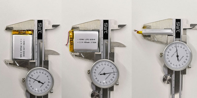
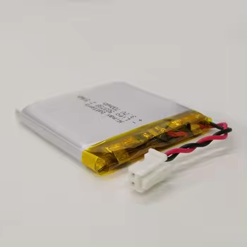
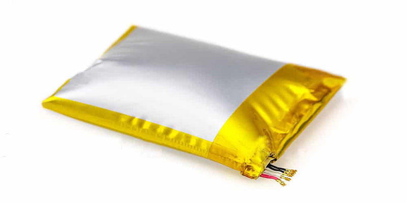
The difference between Li-PO battery and metal casing lithium battery mainly refers to the material of the shell.
Polymer batteries are just liquid lithium-ion batteries with a polymer shell. Structurally, it is packaged with aluminum-plastic film. If a safety hazard occurs, the aluminum-plastic film of the battery will only inflate and crack at most.
The metal casing lithium-ion battery is made of steel or aluminum, and the cover assembly has an explosion-proof power-off function.
Compared with metal casing lithium ion batteries, polymer batteries have more or less advantages in terms of weight, capacity, shape, etc.
However, polymer batteries generally have smaller capacities and higher molding costs. The MOQ is high for customized battery, so the current market share of soft-pack lithium-ion batteries is relatively small.
For more information about lithium batterie/ Li-PO , you can conctact HIMAX, This is a simple introduction to HIMAX:
HIMAX is a professional manufacturer of LiFePO4, lithium-ion, Li-polymer, Ni-MH battery packs, sodium battery. Specifically,marine battery, 12V lead acid replacement battery, 18650 lithium ion battery pack , custom lithium battery pack, li ion customized battery pack, lithium battery for caravan and so on. In summary, we can meet various needs.
We focus on battery solutions for energy storage systems, solar street lighting, RV, electric vehicles, medical equipment, UPS, ETC… With reliable quality, positive service, and competitive price, we have cooperated with many customers from all over the world.
After 12 years of continuous study and exploration, HIMAX has become a global-oriented multinational company integrating R&D and production, providing specialized and customized products. HIMAX has passed ISO9001 quality management system certification, and its products have obtained UL, CE, UN38.3, MSDS, IEC, and other international certifications.
We are looking forward to be your battery partner. OEM & ODM are welcome.
If you have any question, please feel free to contact us:
Name: Dawn Zeng (Director)
E-mail address: sales@himaxelectronics.com
https://himaxelectronics.com/wp-content/uploads/2024/03/3.7.png350350administrator/wp-content/uploads/2019/05/Himax-home-page-design-logo-z.pngadministrator2024-05-15 03:33:072024-05-15 03:56:23What’s the difference between Li-PO battery and metal casing lithium-ion battery?
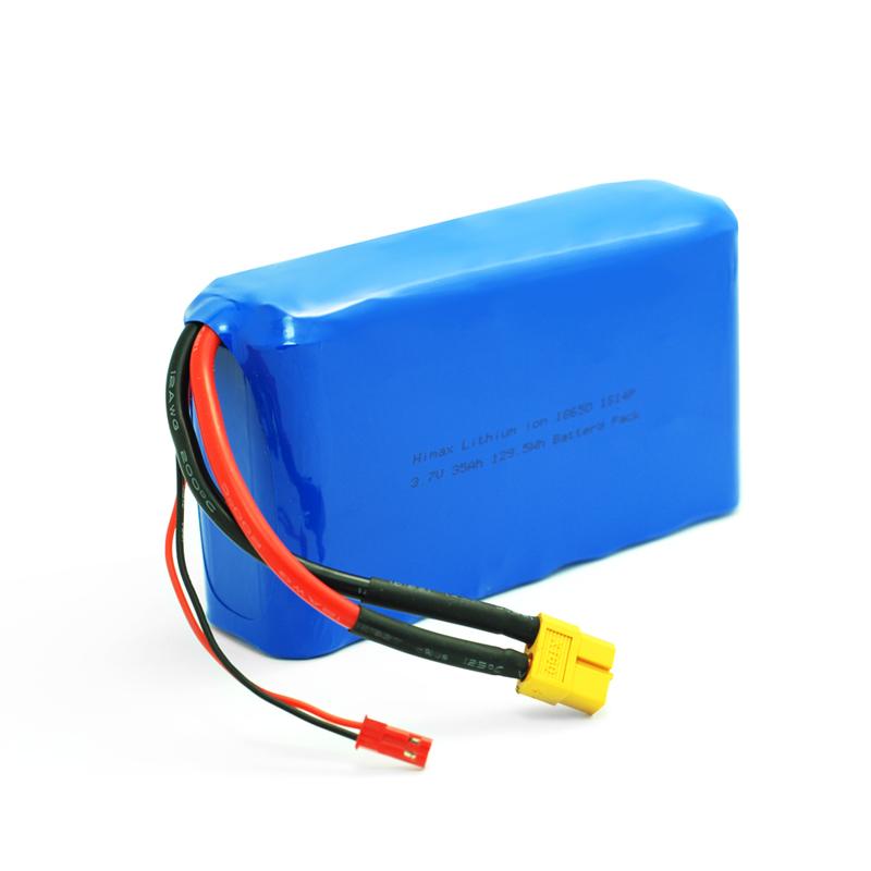
Lithium ion battery is a common rechargeable battery type which is widely used in our daily life.
Lithium-ion batteries have higher energy density and better cycle life, so they are widely used in many application fields, such as electric vehicles, portable electronic devices, monitor, toys, etc.
Here are some susggestions when using lithium-ion batteries:
Charging: Use the recommended charger and charging cable and follow the manufacturer’s charging guidelines. Do not use inappropriate or inferior charging equipment to avoid problems such as overcharging, over-discharging or overheating.
Temperature control: Avoid exposing lithium ion battery to high or low temperatures. Excessively high temperatures will reduce battery life and may even cause safety issues. At the same time, battery performance will also be affected at low temperatures.
Avoid overcharging and discharging: Try to avoid charging and discharging lithium-ion batteries to the limit. Overcharging or overdischarging can negatively affect battery life. Use professional battery management systems or devices to monitor the charging and discharging process to ensure operations within a safe range.
Prevent physical damage: Lithium-ion batteries are relatively fragile and should be protected from physical damage such as impact, crushing, and bending to ensure their normal function and safety.
Water and Moisture Resistant: Lithium batteries are very sensitive to moisture. Avoid immersing the battery in water or exposing it to moisture to prevent safety risks such as battery performance degradation or circuit short circuits.
Storage conditions: When not in use for a long time, the lithium-ion battery should be charged to about 50% and stored in a dry, ventilated, and temperature-friendly environment to extend its life.
Please follow the instructions and recommendations provided by the manufacturer. If you have any questions or confusion about the use of lithium batteries, please consult the manufacturer for accurate guidance.
If you have any question, please feel free to contact us:
Name: Dawn Zeng (Director)
E-mail address: sales@himaxelectronics.com
https://himaxelectronics.com/wp-content/uploads/2020/04/li-ion-batteries.jpg750750administrator/wp-content/uploads/2019/05/Himax-home-page-design-logo-z.pngadministrator2024-04-05 03:55:052024-04-25 15:36:16Precautions for daily use of lithium batteries
Li ion customized battery packs are a widely used class of rechargeable batteries in today’s world. One of the processes that can hamper the functioning of these batteries is an internal short circuit caused by direct contact between the cathode and anode (the conductors that complete the circuit within a battery).
To avoid this, separators composed of polyolefins—a type of polymer—can be employed to maintain separation. However, these separators can melt at higher temperatures, and the inadequate absorption of electrolytes (essential for conveying charges between electrodes) can result in short circuits and diminished efficiency. To tackle these issues, several different methods have been proposed.
One such method is to apply ceramic coatings on the separators to improve the way they handle pressure and heat. However, this can increase the thickness of the separators, reduce their adhesion, and harm battery performance. Another technique is to use polymer coatings, in a process known as graft polymerization. This involves the attachment of individual units (monomers) to the separators to give them the desired qualities.
A recent study published in Energy Storage Materials now demonstrates successful graft polymerization on a polypropylene (PP) separator, incorporating a uniform layer of silicon dioxide (SiO2). The discovery is the result of a joint study that including Assistant Professor Jeongsik Yun from the Department of Energy and Chemical Engineering at Incheon National University.
Dr. Yun was motivated by the need for high-performance battery materials in electric vehicles to achieve longer driving ranges, an area he has been actively working on. Beyond improving battery performance, his goal is to ease consumer concerns about battery explosions, potentially influencing their decisions to embrace electric vehicles.
According to him, “Battery explosions are frequently initiated from the melting of a separator. The commercial battery separator is made of polyolefins, a class of polymers which are vulnerable to heat. We therefore aimed to improve the thermal stability of the commercial separators by coating them with thermally robust materials such as SiO2 particles.”
In this study, a PP separator was modified in several ways. Initially, it was coated with a layer of polyvinylidene fluoride, a chemical chosen to enhance electrolyte affinity and thermal stability, while also introducing grafting reaction sites. Then, the separator underwent grafting with methacrylate molecules, followed by a final coating with SiO2 particles. These modifications made the separator stronger and more resistant to heat, suppressed the growth of lithium dendrites, and helped improve the cycling performance.
The modifications not only preserved the energy storage of li ion customized battery packs per unit volume, but also outperformed other coating methods in cell performance. This technique thus shows promise for creating robust separators and advancing the use of li ion customized battery packs in electric vehicles and energy storage systems.
“We hope that the results of this study can enable the development of high-safety lithium batteries. We believe that the thermal stability of these batteries will greatly benefit the current fire-sensitive electric vehicle field. In the long term, this can motivate people to choose electric vehicles and in urban areas, reduce the suffering of people from breathing in the polluted air generated by the internal combustion engines,” envisions Dr. Yun.
In summary, this study presents a reliable method for creating an innovative and durable separator for lithium-ion batteries, potentially paving the way for a greener future.
More information: Jaewon Park et al, Ultra-thin SiO2 nanoparticle layered separators by a surface multi-functionalization strategy for Li-metal batteries: Highly enhanced Li-dendrite resistance and thermal properties, Energy Storage Materials (2023). DOI: 10.1016/j.ensm.2023.103135
With the development of custom lithium battery pack , the cause of lithium polymer battery bulge has many reasons. According to experimental research and development experience, researchers has concluded 3 major reasons :
. During battery cycling, the battery electrode expansion caused the battery thickness increased.
. Due to the gas production from electrolyte oxidation and decomposition cause battery bulge.
. Bulging caused by production process defects, such as sealing of the battery not tight enough cause the introduced moisture and damaged corners.
At the different custom lithium battery pack systems, the main reason of battery thickness change is different, such as the negative system of LTO battery, the bulge main reason is gas bulge; at graphite negative system, the thickness of the electrode and production of the gas all have a promoting effect.
Electrode thickness change
During charge battery pack cell thickness increase is mainly attribute to the expansion of negative, positive bulge rate is only 2% to 4%, negative electrode normally assemble by composition of graphite, adhesive, and conductive carbon, among them graphite itself bulge rate reached 10%, the reason that cause of graphite electrode bulge are mainly included : SEI film formation, State of Charge, Production process parameters and other influencing factors.
(1) SEI film formation; During the first charging and discharging process of li ion customized battery packs, the electrolyte undergoes a reduction reaction at the solid-liquid phase interface of the graphite particles, forming a passivation layer (SEI film) covering the surface of the electrode material. The generation of the SEI film cause the thickness of the anode is significantly increased, and the thickness of the cell is increased by about 4% due to the formation of the SEI film. From the perspective of the long-term cycle process, according to the physical structure and specific surface of different graphites, the dissolution of SEI and the dynamic process of new SEI production will occur during the cycle process. For example, flake graphite has a greater expansion rate than spherical graphite.
(2) State of charge; During the cycle of the custom lithium battery pack cell, the volume expansion of the graphite anode has a good periodic function relationship with the SOC of the cell, that is, with the continuous insertion of lithium ions in the graphite (the increase of the SOC of the cell) the volume Gradually expand, when li ion customized battery packs are released from the graphite anode, the SOC of the cell gradually decreases, and the volume of the corresponding graphite anode gradually shrinks.
(3) Process parameters; From the perspective of process parameters, the compaction density has a great influence on the graphite anode. During the cold pressing process of the pole piece, a large compressive stress is generated in the graphite anode film layer, and this stress is baked at high temperature in the subsequent pole piece. It is difficult to completely release the waiting process. When the battery cell is being charged and discharged cyclically, due to the joint action of multiple factors such as the insertion and extraction of lithium ions, and the swelling of the electrolyte on the adhesive, the diaphragm stress is released during the cycle and the expansion rate increases. On the other hand, the size of the compaction density determines the void capacity of the anode film layer. The large pore capacity in the film layer can effectively absorb the expanded volume of the pole piece. The small void capacity means that when the pole piece expands, there is not enough space to absorb the expansion. The generated volume, at this time, can only expand to the outside of the film layer, which is manifested as the volume expansion of the anode sheet.
(4) Other factors The bonding strength of the adhesive (adhesive strength of the adhesive, graphite particles, conductive carbon and the interface between the current collectors), charge and discharge rate, swelling of the adhesive and electrolyte, graphite particles The shape and bulk density of the anode, as well as the increase in the volume of the electrode piece caused by the failure of the adhesive during the cycle, all have a certain degree of influence on the expansion of the anode.
Expansion rate calculation:
The calculation of the expansion rate uses the quadratic element to measure the dimensions of the anode sheet in the X and Y directions, and the micrometer to measure the thickness in the Z direction. They are measured after the sheet is punched and the battery is fully charged.
Effect of compaction density and coating quality on negative electrode expansion
Taking compaction density and coating quality as factors, three different levels were selected for each, and a full factorial orthogonal experimental design was carried out (as shown in Table 1), and the other conditions of each group were the same.
It can be seen from Figure 2(a) and (b) that after the cell is fully charged, the expansion rate of the anode sheet in the X/Y/Z direction increases with the increase of the compaction density. When the compacted density increases from 1.5g/cm3 to 1.7g/cm3, the expansion rate in the X/Y direction increases from 0.7% to 1.3%, and the expansion rate in the Z direction increases from 13% to 18%. It can be seen from Figure 2(a) that under different compaction densities, the expansion rate in the X direction is greater than that in the Y direction. The reason for this phenomenon is mainly caused by the cold pressing process of the pole piece. When rolling, according to the law of least resistance, when the material is subjected to external force, the material particles will flow along the direction of least resistance.
When the anode sheet is cold-pressed, the direction with the least resistance is the MD direction (the Y direction of the pole piece, as shown in Figure 3). The stress is easier to release in the MD direction, while the TD direction (the X direction of the pole piece) has greater resistance, and the roller The stress is not easy to release during the compression process, and the stress in the TD direction is larger than that in the MD direction. Therefore, after the electrode sheet is fully charged, the expansion rate in the X direction is greater than the expansion rate in the Y direction. On the other hand, the compaction density increases and the pore capacity of the electrode sheet decreases (as shown in Figure 4). When charging, there is no There is enough space to absorb the expanded volume of graphite, and the external manifestation is that the entire pole piece expands in the three directions of X, Y, and Z. It can be seen from Figure 2(c) and (d) that the coating mass increases from 0.140g/1,540.25mm2 to 0.190g/1,540.25mm2, and the expansion rate in the X direction increases from 0.84% to 1.15%, Y The directional expansion rate increased from 0.89% to 1.05%, and the Z-direction expansion rate trend was opposite to the X/Y direction change trend, showing a downward trend, decreasing from 16.02% to 13.77%. It shows that the expansion of graphite anode presents one after another in the three directions of X, Y and Z, and the change of coating quality is mainly reflected in the significant change of film thickness. The above anode change rule is consistent with the literature results, that is, the smaller the ratio of the current collector thickness to the film thickness, the greater the stress in the current collector.
Effect of Copper Foil Thickness on Negative Electrode Expansion
Two influencing factors are selected: copper foil thickness and coating quality. The copper foil thickness levels are 6 and 8 μm respectively. The anode coating qualities are 0.140g/1, 540.25mm2 and 0.190g/1, 540.25mm2 respectively. The compacted densities are all 1.6g/cm3, other experimental conditions in each group are the same, and the experimental results are shown in Figure 5. It can be seen from Figure 5(a) and (c) that under two different coating qualities, the expansion rate of the 8 μm copper foil anode sheet in the X/Y direction is less than 6 μm, indicating that the thickness of the copper foil increases due to the increase in its elastic modulus. (See Figure 6), that is, the resistance to deformation is enhanced, the constraint on the expansion of the anode is enhanced, and the expansion rate is reduced. According to the literature, under the same coating quality, when the thickness of the copper foil increases, the ratio of the current collector thickness to the film thickness increases, the stress in the current collector becomes smaller, and the expansion rate of the pole piece becomes smaller. In the Z direction, the change trend of the expansion rate is completely opposite. It can be seen from Figure 5(b) that as the thickness of the copper foil increases, the expansion rate increases. From the comparison of Figure 5(b) and (d), it can be seen that when the coating quality When increasing from 0.140g/1 and 540.25mm2 to 0.190g/1 and 540.25mm2, the copper foil thickness increases and the expansion rate decreases. Although the increase in the thickness of the copper foil is beneficial to reducing its own stress (high strength), it will increase the stress in the film layer, resulting in an increase in the Z-direction expansion rate, as shown in Figure 5(b); as the coating quality increases, thick copper Although the foil promotes the increase in the stress of the film layer, it also enhances the restraint ability of the film layer. At this time, the restraint force is more obvious and the expansion rate in the Z direction decreases.
Effect of graphite type on negative electrode expansion
Five different types of graphite were used for experiments (see Table 2). The coating mass was 0.165g/1, 540.25mm2, the compaction density was 1.6g/cm3, and the copper foil thickness was 8μm. Other conditions were the same. The experimental results are shown in Figure 7 . As can be seen from Figure 7(a), the expansion rates of different graphites in the X/Y direction vary greatly, with a minimum expansion rate of 0.27% and a maximum of 1.14%. The Z-direction expansion rate has a minimum expansion rate of 15.44% and a maximum of 17.47%. , the expansion in the Z direction is small, consistent with the results analyzed in Section 2.2. Among them, the battery core using A-1 graphite showed serious deformation, with a deformation ratio of 20%. The other groups of battery cores did not show deformation, indicating that the X/Y expansion rate has a significant impact on the battery core deformation.
In conclusion
(1) When the compaction density is increased, the expansion rate of the anode sheet increases along the X/Y and Z directions during the full charging process, and the expansion rate in the X direction is greater than the expansion rate in the Y direction (the X direction is the cold pole plate The direction of the roller axis during the pressing process, and the Y direction is the direction of the machine belt).
(2) When the coating quality is increased, the expansion rate in the X/Y direction increases, and the expansion rate in the Z direction decreases; increasing the coating quality will lead to an increase in the tensile stress in the current collector.
(3) Improving the strength of the current collector can suppress the expansion of the anode sheet in the X/Y direction.
(4) Different types of graphite have large differences in expansion rates in the X/Y and Z directions, and the expansion in the X/Y direction has a greater impact on the deformation of the battery.
Bulging caused by battery gas
The internal gas production of the custom lithium battery pack is another important cause of battery bulging. Whether the custom lithium battery Pack is cycled at normal temperature, cycled at high temperature, or left at high temperature, it will produce gas bulging to varying degrees. During the first charge and discharge process of the battery, an SEI (Solid Electrolyte Interface) film will be formed on the surface of the electrode. The formation of the negative SEI film mainly comes from the reduction and decomposition of EC (Ethylene Carbonate). While alkyl lithium and Li2CO3 are generated, a large amount of CO and C2H4 will be generated. DMC (Dimethyl Carbonate) and EMC (Ethyl Methyl Carbonate) in the solvent will also form RLiCO3 and ROLi during the film formation process, accompanied by the production of CH4, C2H6, C3H8 and other gases and CO gas. In the PC (Propylene carbonate)-based electrolyte, relatively more gas is produced, mainly C3H8 gas generated by the reduction of PC. The lithium iron phosphate soft pack battery swells most severely after charging at 0.1C during the first cycle. It can be seen from the above that the formation of SEI will be accompanied by the generation of a large amount of gas, which is an inevitable process. The presence of H2O in impurities will destabilize the P-F bond in LiPF6 and generate HF. HF will cause instability in the battery system and produce gas. The presence of excess H2O will consume Li+ and generate LiOH, LiO2 and H2, resulting in gas generation. Gas will also be produced during storage and long-term charging and discharging. For sealed lithium-ion batteries, the occurrence of a large amount of gas will cause the battery to swell, thereby affecting the performance of the battery and shortening the service life of the battery. The main reasons why batteries produce gas during storage are as follows: (1) The H2O present in the battery system will cause the generation of HF, causing damage to the SEI. O2 in the system may cause oxidation of the electrolyte, resulting in the generation of a large amount of CO2; (2) If the SEI film formed for the first time is unstable, the SEI film will be destroyed during the storage stage, and the repair of the SEI film will release hydrocarbons. Class-based gases. During the long-term charge and discharge cycle of the battery, the crystal structure of the positive electrode material changes. Factors such as uneven point potential on the electrode surface cause the potential of some points to be too high. The stability of the electrolyte on the electrode surface decreases, and the electrode surface film continues to thicken. This increases the electrode interface resistance and further increases the reaction potential, causing the electrolyte to decompose on the electrode surface to produce gas, and the positive electrode material may also release gas.
In different systems, the degree of custom lithium battery pack bulging is different. In graphite anode system batteries, the main reasons for gas bulging are SEI film formation, excessive moisture in the cell, abnormal formation process, poor packaging, etc. As mentioned above, in the lithium titanate anode system, the industry generally believes that Li4Ti5O12 The swelling of batteries is mainly caused by the material itself easily absorbing water, but there is no definite evidence to prove this speculation. Xiong et al. from Tianjin Lishen Battery Company pointed out in the abstract of the paper of the 15th International Electrochemistry Conference that the gas components include CO2, CO, alkanes and a small amount of olefins, but no data support was given for their specific composition and proportion. Belharouak et al. used gas chromatography-mass spectrometry to characterize battery gas production. The main component of gas is H2, as well as CO2, CO, CH4, C2H6, C2H4, C3H8, C3H6, etc.
Gas composition of Li4Ti5O12/LiMn2O4 battery cycled at 30, 45, 60 ℃ for 5 months
The electrolyte system generally used in lithium-ion batteries is LiPF6/EC:EMC, where LiPF6 has the following balance in the electrolyte.
PF5 is a strong acid that easily causes the decomposition of carbonates, and the amount of PF5 increases with temperature. PF5 helps the electrolyte decompose to produce CO2, CO and CxHy gases. Calculations also show that the decomposition of EC produces CO and CO2 gases. C2H4 and C3H6 are generated by the redox reaction of C2H6 and C3H8 with Ti4+ respectively, while Ti4+ is reduced to Ti3+. According to relevant research, the generation of H2 comes from trace amounts of water in the electrolyte, but generally the water content in the electrolyte is about 20×10-6, which is harmful to the production of H2 gas. Wu Kai of Shanghai Jiao Tong University’s experiment chose graphite/NCM111 as a battery with very low contribution, and concluded that the source of H2 is the decomposition of carbonate under high voltage.
Abnormal processes lead to gas generation and expansion
Poor encapsulation, the proportion of flattened battery cells caused by poor encapsulation has been greatly reduced. We have already introduced the causes of poor sealing on the three sides of Top sealing, Side sealing and Degassing. Poor sealing on any side will cause battery cells. Most of them are Top sealing and Degassing. Top sealing is mainly caused by poor sealing of the Tab position, and Degassing is mainly caused by delamination. (Including the separation of PP and Al due to the influence of electrolyte and gel). Poor packaging causes moisture in the air to enter the battery core, causing the electrolyte to decompose and generate gas.
The surface of the Pocket is damaged, and the custom lithium battery pack core is abnormally damaged or artificially damaged during the flow-drawing process, resulting in damage to the Pocket (such as pinholes), allowing moisture to enter the interior of the battery core.
Corner damage, due to the special deformation of aluminum at the folded corners, the shaking of the air bag will distort the corners and cause Al damage (the larger the custom lithium battery pack core, the larger the air bag, the easier it is to be damaged), and lose the barrier effect on water. Wrinkle glue or hot melt glue can be added to the corners to alleviate the problem. In addition, it is forbidden to use air bags to move the battery cells during the various processes after top sealing. Pay more attention to the operation method to prevent the battery cells from swinging on the aging board.
The water content inside the battery cell exceeds the standard. Once the water content exceeds the standard, the electrolyte will fail and generate gas after formation or degassing. The main reasons for excessive water content inside the battery include: excessive water content in the electrolyte, excessive water content in the bare battery core after baking, and excessive humidity in the drying room. If it is suspected that excessive water content is causing flatulence, a retrospective inspection of the process can be carried out.
The formation process is abnormal, and the wrong formation process will cause the battery core to bloat.
The SEI film is unstable, and the battery cell’s emission function is slightly bloated during the charge and discharge process of the capacity test.
Overcharge and overdischarge, due to the abnormality of the process or machine or protection board, the battery core will be overcharged or over-discharged, and the battery core will be severely inflated.
Short circuit. Due to operational errors, the two tabs of the charged battery cell are in contact with each other and short circuit occurs. The custom lithium battery pack cell will inflate and the voltage will drop rapidly, and the tab will be burned black.
Internal short circuit, the short circuit of cathode and anode inside the battery core causes the battery core to discharge rapidly and heat up, and at the same time, it is severely gassed. There are many reasons for internal short circuit: design problems; isolation film shrinkage, curling, damage; Bi-cell misalignment; burrs piercing the isolation film; excessive clamp pressure; For example, due to insufficient width, the ironing machine excessively squeezed the battery body, resulting in short-circuiting of the cathode and anode, and flatulence.
Corrosion, the battery core corrodes, the aluminum layer is consumed by the reaction, loses its barrier effect on water, and flatulence occurs.
Vacuum pumping is abnormal, and the vacuum degree is abnormal due to system or machine reasons. Degassing is not thorough; the heat radiation area of Vacuum Sealing is too large, causing the degassing bayonet to be unable to effectively pierce the pocket bag, resulting in unclean vacuuming.
Measures to suppress abnormal gas production
Suppressing abnormal gas production needs to start from two aspects: material design and manufacturing process.
First of all, it is necessary to design and optimize the material and electrolyte system to ensure the formation of a dense and stable SEI film, improve the stability of the cathode material, and suppress the occurrence of abnormal gas production.
For the treatment of electrolyte, the method of adding a small amount of film-forming additives is often used to make the SEI film more uniform and dense, and to reduce the SEI film shedding during battery use and the custom lithium battery pack bulging caused by gas production during regeneration. Related studies have been reported and used in practice. For example, Cheng Su from Harbin University of Science and Technology reported that the use of film-forming additive VC can reduce battery bloating. However, most studies have focused on single-component additives, and the effect is limited. Cao Changhe and others from East China University of Science and Technology used VC and PS as a new type of electrolyte film-forming additive, and achieved good results. The gas production of the battery was significantly reduced during high-temperature storage and cycling. Studies have shown that the SEI film component formed by EC and VC is linear alkyl lithium carbonate, and the alkyl lithium carbonate attached to LiC is unstable at high temperature, and decomposes to generate gas (such as CO2, etc.) to cause battery swelling. The SEI film formed by PS is lithium alkyl sulfonate. Although the film has defects, it has a certain two-dimensional structure and is relatively stable when attached to LiC at high temperatures. When VC and PS are used in combination, PS forms a defective two-dimensional structure on the surface of the negative electrode when the voltage is low, and as the voltage increases, VC forms a linear structure of alkyl lithium carbonate on the surface of the negative electrode, and the alkyl lithium carbonate fills In the defects of the two-dimensional structure, an SEI film with a network structure stably attached to LiC is formed. The SEI membrane with this structure greatly improves its stability and can effectively suppress gas production caused by membrane decomposition.
In addition, due to the interaction between the positive electrode custom lithium battery Packcobalt oxide material and the electrolyte, the decomposition products will catalyze the decomposition of the solvent in the electrolyte. Therefore, surface coating of the positive electrode material can not only increase the structural stability of the material, but also reduce the interaction between the positive electrode and the electrolyte. The contact with the liquid reduces the gas generated by the catalytic decomposition of the active positive electrode. Therefore, forming a stable and complete coating layer on the surface of cathode material particles is also a major development direction at present.
If you have any question, please feel free to contact us:
Name: Dawn Zeng (Director)
E-mail address: sales@himaxelectronics.com
https://himaxelectronics.com/wp-content/uploads/2021/01/Causes-of-Lithium-Battery-Swelling.jpg400800administrator/wp-content/uploads/2019/05/Himax-home-page-design-logo-z.pngadministrator2023-09-06 01:18:212024-04-28 15:25:55The summary of the reason Lithium Polymer battery bulge
In this issue, we are going to discuss the challenges of Lithium Polymer batteries especially since they suffer from a shorter life if not cared for properly.
Luckily, it’s easy to make sure your Lithium Polymers last as long as they should, allowing you to save on money and the hassle.
When should you charge?
The first challenge in taking care of Lithium Polymers is knowing when to charge them.
In general, Lithium Polymers have a lifespan of somewhere between 300 and 500 charge cycles, from full to empty and back to full again.
But you can help maximize that life by charging before the battery is empty.
Unlike other rechargeable batteries like Ni-cads, Lithium Polymers do not have a memory. So, there is no need to wait until the battery is empty before charging.
In fact, with Lithium Polymer batteries, recharging before the battery is 80% depleted can help prolong the battery life, and is a more efficient way to charge too.
Such as cell phones and laptops, don’t wait until the screen dies before you charge. Charge whenever you get an opportunity.
LiPos are temperature sensitive
You should avoid charging when the battery is below 10ºC/50ºF as the chemical makeup of the battery means it is much less efficient when below that level.
Heat is just as important, hot Lithium Polymer batteries don’t take charge well either, so always ensure they have cooled down after use before charging.
In order to prolong the life of your battery, it is just as important to store them when they’re not being used.
In fact, for Lithium Polymers, this may be the area where most problems occur.
The temptation with batteries is to charge them up before putting them away, so they are ready to go the next time you need them, but for Lithium Polymer batteries without a BMS, this is a disaster.
Storage
Thankfully, Lithium Polymer chargers often have a ‘storage’ option for charging, which gives the battery a suitable charge for storage.
Fully charged batteries can expand when stored for an extended period, rendering them unusable, so if you have a storage option, make sure you use it.
Because Lithium Polymer batteries lose less than 1% of charge per month when stored, you will not be in danger of allowing them to discharge too far unless stored for a very long time.
However, it is important to remember that Lithium Polymers do not like being at extremely low voltages from a complete discharge, it can not only shorten life but also damage the battery in some circumstances, so keep an eye on those in storage.
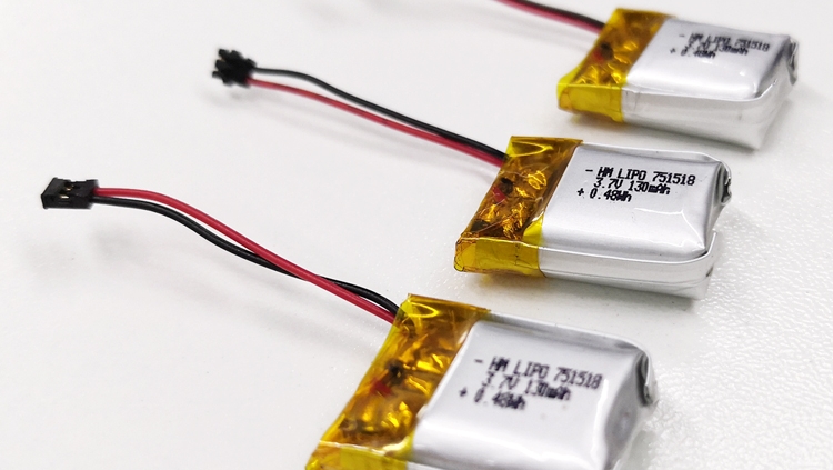
https://himaxelectronics.com/wp-content/uploads/2021/04/130mah-3.7v-battery.jpg750750administrator/wp-content/uploads/2019/05/Himax-home-page-design-logo-z.pngadministrator2021-06-16 08:54:282024-04-26 06:05:24How to Prolong Your Lithium Polymer Batteries
The most common drone safety issues, next to pilot error are related to battery failures. If you’ve ever experienced battery failure during charging, storage, or operation, then you understand how alarming and potentially dangerous it can be.
Over 200 injuries related to drone battery incidents were reported to the U.S. Consumer Product Safety Commission between 2012 and 2017. The reported incidents involved fire, smoke, and even explosions. It’s likely that countless other incidents went unreported because they didn’t end in an emergency room visit.
In order to ensure battery safety, it’s critical as a commercial drone operator to purchase your batteries and battery management systems from a reputable, safety-minded provider.
Why Do Drone Batteries Fail?
While some drone battery failures occur for reasons that no one could predict or discover, most incidents could have been avoided with proper care and maintenance of your battery fleet. To reduce your potential risk drone users should be well-versed in battery safety practices.
Manufacturers are also responsible for the safety of each battery. In order to provide reliable performance and increased safety, reputable battery manufacturers employ high-quality materials and precise manufacturing and quality control processes. When manufacturers cut corners, they reduce overall battery safety. Quality costs money, so when a battery price seems too good to be true, it probably is.
Choosing Batteries for Drone Safety
Know the Manufacturer
Reputable manufacturers are transparent and provide plenty of information about their company and practices. Research the quality of materials and designs used to manufacture their drone batteries. If you’re considering a discounted battery purchase but can’t find much information about the company that makes it, it’s best to reconsider. Make sure that your supplier is located within the United States, if you need support or have a question, you want to have an English speaking support staff to answer your call.
Focus on Safety Features
In the interests of the bottom line, some manufacturers strip away “expendable” safety features to create budget batteries. You might be tempted by those batteries when you’re browsing online, but be careful – always review the product description carefully and note the safety features listed. You’ll probably need to visit the manufacturer’s website to find a complete list of features and related details.
Choose the Right Charger
A top-of-the-line drone battery plugged into a low-quality charger will inevitably cause headaches and compromise battery safety. It’s best to choose a “smart” or programmable battery charger. You’re better able to manage your drone batteries when you have important charging data at your disposal. It’s also best to use batteries and chargers produced by the same manufacturer.
Best Practices for Battery Safety
How to Store
It’s recommended that you drain batteries to 40-60 percent of their full capacity before storing them for more than ten days. If you’re planning to store them for fewer than 10 days, drain them to 60-80 percent of their capacity. Partially draining batteries reduces stress on them and extends their working life. Never store your batteries for more than three months without charging them.
It’s best to store batteries in a dry location at room temperature. Before tucking those batteries away, inspect them for a puncture, puffing, or other abnormal physical features that indicate an unhealthy battery.
How to Charge
Most incidents occur while the battery is charging, which is why it’s recommended to charge your drone batteries at a 1C charge rate. To find this rate take the milliamp hour capacity rating of your battery divide it by 1000. For example, a 22,000 millamp battery should be charged at 22amps. Always monitor your batteries during the charging process and only charge your batteries on a non-flammable surface located away from any flammable materials. While battery fires are rare, a damaged battery or incorrect charge settings can cause a battery to swell, expand and worst-case scenario catch fire. Being prepared with a suitable fire extinguisher and ready to react if you see signs of trouble is critical.
How to Operate
How and where you fly your drone can impact its battery life. It’s best to avoid flying in extreme temperatures. Refer to the manufacturer’s instructions for specific information about safe flight temperatures for your drone. The generally accepted rule is to fly within the range of 14 °F to 104 °F for optimal drone safety.
Using an appropriately sized battery for your drone is critical for overall safety. Using a battery that does not provide enough power for your drone will not only adversely affect battery life but can lead to overheating of the pack and thermal runaway, a dangerous process that devours the battery. Thermal runaway is a heat-induced chemical reaction that intensifies and continues to raise internal temperatures until all the reactive agents within the cell are consumed.
How to Transport
Secure your batteries with padding during transport to prevent them from hitting against other batteries or objects. Also, make sure that any exposed leads or connectors are protected from arcing or shorting. Cover with tape or use specifically designed covers to avoid issues.You can purchase cases and backpacks designed specifically for this purpose. If you’re taking them with you on a plane, remember to pack your drone and batteries in your carry-on baggage and review the current FAA rules for batteries. Regulations for transportation of batteries are also subject to the carrier by carrier-specific rules. Always check with your airline before you try and fly with your drone or batteries.
Himax Provides Safe, Custom-Designed Batteries for Commercial Use
Himax values safety above their bottom line, which is why they offer custom-designed batteries that are produced with superior materials and high-tech safety features.
Custom-Designed Lithium-Ion Batteries for OEM Applications
Himax’s custom-designed batteries were created for professional, commercial, and industrial use. Their robust composition will withstand the most rigorous, unmanned applications without compromising on energy density and weight. They offer a wide range of custom battery designs, which ensures that you will receive a product that meets your unique and precise requirements.
Why does custom design matter for drone safety? Himax’s custom-designed batteries accommodate targeted operating temperatures and discharge voltages. When your drone battery is designed with a specific application in mind, it will operate more efficiently and safely in the conditions under which it will actually be used.
Battery Safety Certifications
Himax products are produced with high-quality materials that ensure durability, extend battery life, and prevent battery failure. Himax can assist with manufacturing to meet and exceed any required safety compliance schemes. We have experience with UN38.3, CE, RoHS, and FCC. We have multiple NRT laboratories that can provide testing services.
Safety Features
Himax’s commercial series of batteries provides the most advanced battery management system (BMS) available on the market. These “smart” batteries include an embedded BMS. This active BMS system helps extend battery life, tracks, and stores critical battery information. The system also allows for additional safety features include real-time fault detection, battery lockout protocol, five LED Indicators, and the ability to capture and store KPIs, which include:
Remaining capacity
State of charge
Cell voltage
Pack voltage
Current draw
Cell temperatures
Faults
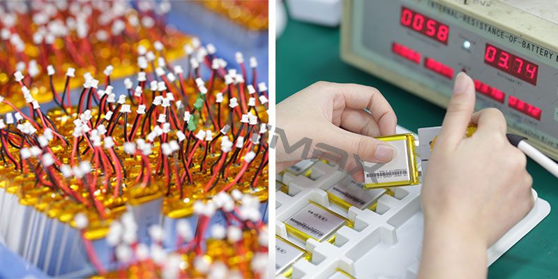
In addition to careful construction and critical safety features, Himax inspects all products before they leave the factory to ensure each one meets their quality and safety standards.
https://himaxelectronics.com/wp-content/uploads/2021/05/Drones.jpg400800administrator/wp-content/uploads/2019/05/Himax-home-page-design-logo-z.pngadministrator2021-05-05 03:03:052024-04-26 06:04:20Safety Issues When Using Drones
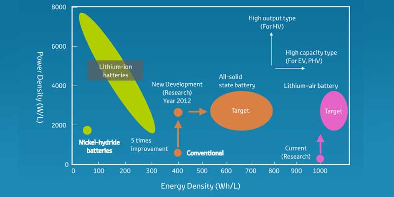
The energy density of batteries can be displayed in two different ways: gravimetric energy density and volumetric energy density.
The gravimetric energy density is the measure of how much energy a battery contains in proportion to its weight. This measurement is typically presented in Watt-hours per kilogram (W-hr / kg). The volumetric energy density, on the other hand, is compared to its volume and is usually expressed in watt-hours per liter (W-hr / L). Generally, we refer to battery energy density as gravimetric ( weight ) energy density, and watt-hour is a measure of electrical energy, equivalent to one hour, one watt of consumption.
In contrast, the power density of a battery is a measure of how fast energy can be delivered, not how much stored energy is available. Energy density is often confused with power density, so it is important to understand the difference between the two.
Calculation formula
The energy density of a battery can be simply calculated using this formula: Nominal Battery Voltage (V) x Rated Battery Capacity (Ah) / Battery Weight (kg) = Specific Energy or Energy Density (Wh / kg).
LiCo and LiFePO4 Batteries’ energy density
Generally speaking, LiCo batteries have an energy density of 150-270 Wh/kg. Their cathode is made up of cobalt oxide and the typical carbon anode with a layered structure that moves lithium-ions from anode to the cathode and back. This battery is popular for its high energy density, and it’s typically used in consumer products such as cell phones and laptops.
LiFe batteries, on the other hand, have an energy density of 100-120 Wh/kg. Although this is lower than LiCo batteries, it is still considered higher in the rechargeable battery category. LiFe batteries use iron phosphate for the cathode and a graphite electrode combined with a metallic backing for the anode. They are ideal for heavy equipment and industrial applications because of their better ability to withstand high and low temperatures.
Conclusion
As far as the single-cell is concerned, the positive and negative materials and production process of the battery will affect the energy density, so it is necessary to develop more reasonable materials and better manufacturing technology to obtain a more efficient battery.
https://himaxelectronics.com/wp-content/uploads/2021/04/High-Energy-Density-Battery.jpg400800administrator/wp-content/uploads/2019/05/Himax-home-page-design-logo-z.pngadministrator2021-04-30 07:59:582024-04-26 06:19:26What Is The High Energy Density Battery?
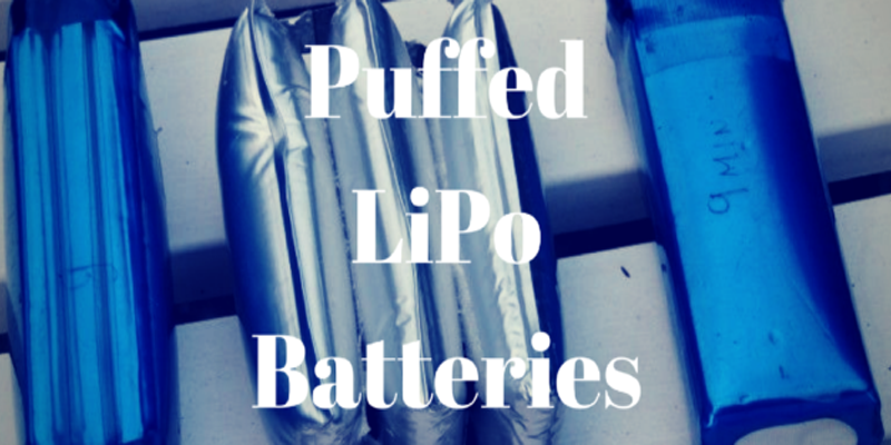
Anybody who uses lipos will eventually encounter a puffy or swollen battery.
And the first question that inevitably comes up is “What should I do?”
This post is all about what causes that swelling and what to do when it happens to one of your lipos.
Are Swollen Lipo Batteries Dangerous?
Yes. Next question.
Seriously, there are so many examples of puffed batteries that start on fire that this shouldn’t even be a question.
That doesn’t mean that every battery that is puffed is going to explode as soon as you use it but it does mean that a high enough percentage of them are going to be dangerous that it isn’t worth the risk.
What Causes Lipo Batteries to Puff Up?
Gas generation in lithium ion batteries is a normal thing. Even if you don’t abuse your battery, the normal everyday use of your battery will generate gas through a process called electrolyte decomposition.
The electrolyte decomposition occurs even faster if you overdischarge a battery or overheat a battery.
What is electrolyte decompostion?
Simply put, a battery is made of three things: the anode, the cathode and the electrolyte. The cathode and the anode are the positive and negative terminals on your battery.
The electrolyte is a chemical inside the battery that allows charged ions to flow from the anode to the cathode during discharge (and the other way during charging).
Electrolyte decomposition is what happens when that electrolyte chemically breaks down. So in a lipo battery, as the electrolyte breaks down you end up with lithium and oxygen. This forms lithium oxide on the anode and cathode (depending whether you are charging or discharging).
But what you also end up with is excess oxygen that doesn’t adhere to the anode or cathode. This excess oxygen is part of what causes a battery swell. And oxygen likes to burn. See here for more details. He also goes over some other reasons a battery might swell.
Other gases that can be found in the battery during the normal chemical reactions of a battery are carbon dioxide (CO2) and carbon monoxide (CO). For a technical overview of this, see this paper.
How to Fix a Swollen Battery
Don’t.
Just Don’t.
Dispose of it properly (see below) and buy a new one.
It’s not worth injuring yourself or burning your house down to save a few bucks.
How to Dispose of Puffed Lipo Batteries
The proper way to dispose of a swollen lipo battery is the same as what you would do when you throw out any old battery. You need to discharge it completely first.
The two main methods that people use to discharge a battery completely is to hook it up to a light bulb or to put it in a bucket of saltwater. There are debates about which method is better but I will avoid that debate here for now.
If you decide to hook it up to a light bulb, I would recommend these 12 V, 20 Watt halogen bulbs. They are easy to solder to so you attach lead wires and connector pretty easily. This makes it easy to just plug in your battery to let it discharge. You can hook multiple in parallel to get the discharge rate you want. If you have any questions about this, let me know in the comments.
After you’ve completely discharged the battery, I recommend finding your nearest battery recycling drop-off point and bringing it there. Make sure you call ahead and ask if they accept damaged batteries.
Tips to Avoid a Swollen Battery
Proper charging – Make sure you charge your battery properly using a quality battery charger. For safety, make sure you put your batteries in a lipo bag while charging. If you don’t have a lipo bag, I highly recommend you buy one. For around $10, you can insure that if something does go wrong at will at least be contained.
Don’t over-discharge – Make sure you stop using your battery before the voltage gets to the minimum cut-off voltage.
Heat kills batteries – Don’t use batteries or charge batteries when they are warm. After you’re done using them, give them a little time to cool off before you charge them. And after you are done charging them, give them a little time before you use them.
Proper storage – Do not store your batteries in a hot location. (For example, don’t keep them in the trunk of your car during in the summer.) Store lipo’s at the proper storage voltage. The article I linked to above showed that swelling increased significantly after only 4 hours of storage when batteries were at a state of charge above 80%.
Conclusion
To sum up: As lipo’s age and if they are misused, gases start to form in the battery and cause it to swell. Once you have a puffy lipo, the safe thing to do is to discharge it completely and then recycle it.
If you want to learn more about lipo’s, check out my in-depth lipo battery guide. There I go into a lot of detail about all aspects of lipo’s.
https://himaxelectronics.com/wp-content/uploads/2021/03/Puffed-Lipo-Battery.png400800administrator/wp-content/uploads/2019/05/Himax-home-page-design-logo-z.pngadministrator2021-03-23 02:46:592024-04-26 06:22:34PUFFED LIPO BATTERY: WHY THEY SWELL AND WHAT TO DO ABOUT IT


 The most common drone safety issues, next to pilot error are related to battery failures. If you’ve ever experienced battery failure during charging, storage, or operation, then you understand how alarming and potentially dangerous it can be.