Learn about storage temperatures and state-of-charge conditions.
The recommended storage temperature for most batteries is 15°C (59°F); the extreme allowable temperature is –40°C to 50°C (–40°C to 122°F) for most chemistries.
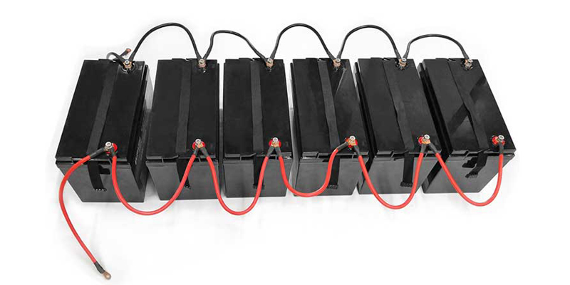
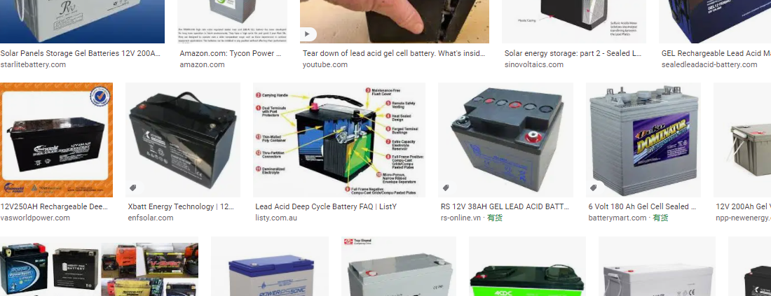
Lead acid
You can store a sealed lead acid battery for up to 2 years. Since all batteries gradually self-discharge over time, it is important to check the voltage and/or specific gravity, and then apply a charge when the battery falls to 70 percent state-of-charge, which reflects 2.07V/cell open circuit or 12.42V for a 12V pack. (The specific gravity at 70 percent charge is roughly 1.218.) Lead acid batteries may have different readings, and it is best to check the manufacturer’s instruction manual. Some battery manufacturer may further let a lead acid to drop to 60 percent before recharge. See BU-903: How to Measure State-of-charge.)
Low charge induces sulfation, an oxidation layer on the negative plate that inhibits current flow. Topping charge and/or cycling may restore some of the capacity losses in the early stages of sulfation. (See BU-804b: Sulfation and How to Prevent it.)
Sulfation may prevent charging small sealed lead acid cells, such as the Cyclone by Hawker, after prolonged storage. These batteries can often be reactivated by applying an elevated voltage. At first, the cell voltage under charge may go up to 5V and draw very little current. Within 2 hours or so, the charging current converts the large sulfate crystals into active material, the cell resistance drops and the charge voltage gradually normalizes. At between 2.10V and 2.40V the cell is able to accept a normal charge. To prevent damage, set the current limit to a very low level. Do not attempt to perform this service if the power supply does not have current limiting. (See BU-405: Charging with a Power Supply.)
Nickel-based
Recommended storage is around 40 percent state-of-charge (SoC). This minimizes age-related capacity loss while keeping the battery operational and allowing for some self-discharge. Nickel-based batteries can be stored in a fully discharged state with no apparent side effect.
Measuring SoC by voltage is difficult on nickel-based batteries. A flat discharge curve, agitation after charge and discharge and temperature affects the voltage. The good news is that the charge level for storage is not critical for this chemistry, so simply apply some charge if the battery is empty and store it in a cool and dry place. With some charge, priming should be quicker than if stored in a totally discharged state.
Nickel-metal-hydride can be stored for 3–5 years. The capacity drop that occurs during storage is partially reversible with priming. Nickel-cadmium stores well. The US Air Force was able to deploy NiCd batteries that had been in storage for 5 years with good recovered capacities after priming. It is believed that priming becomes necessary if the voltage drops below 1V/cell. Primary alkaline and lithium batteries can be stored for up to 10 years with only moderate capacity loss.
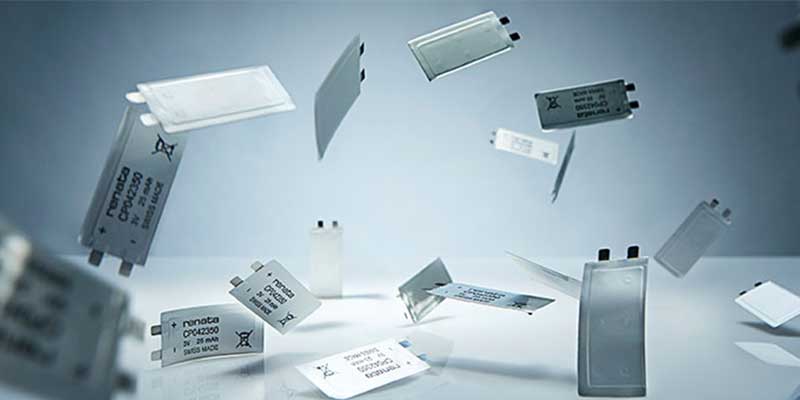
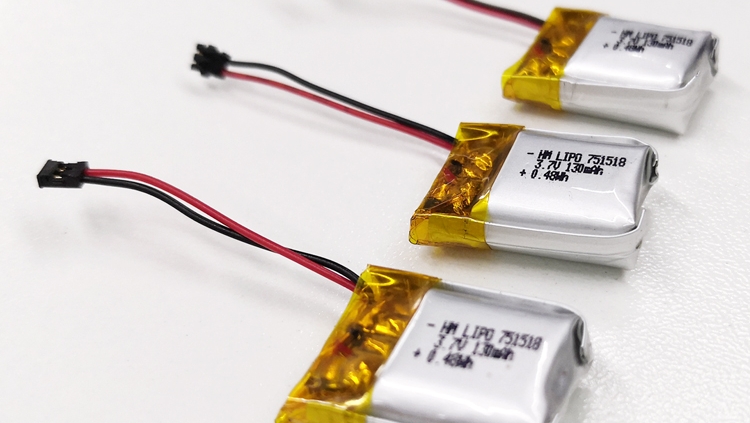
Lithium-based
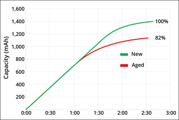
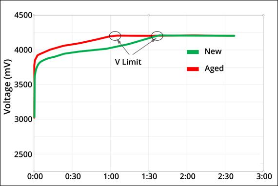
There is virtually no self-discharge below about 4.0V at 20C (68F); storing at 3.7V yields amazing longevity for most Li-ion systems. Finding the exact 40–50 percent SoC level to store Li-ion is not that important. At 40 percent charge, most Li-ion has an OCV of 3.82V/cell at room temperature. To get the correct reading after a charge or discharge, rest the battery for 90 minutes before taking the reading. If this is not practical, overshoot the discharge voltage by 50mV or go 50mV higher on charge. This means discharging to 3.77V/cell or charging to 3.87V/cell at a C-rate of 1C or less. The rubber band effect will settle the voltage at roughly 3.82V. Figure 1 shows the typical discharge voltage of a Li-ion battery.
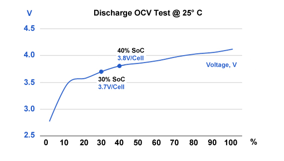
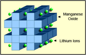
Figure 1: Discharge voltage as a function of state-of-charge. Battery SoC is reflected in OCV. Lithium manganese oxide reads 3.82V at 40% SoC (25°C), and about 3.70V at 30% (shipping requirement). Temperature and previous charge and discharge activities affect the reading. Allow the battery to rest for 90 minutes before taking the reading.
Li-ion cannot dip below 2V/cell for any length of time. Copper shunts form inside the cells that can lead to elevated self-discharge or a partial electrical short. (See BU-802b: Elevated Self-discharge.) If recharged, the cells might become unstable, causing excessive heat or showing other anomalies. Li-ion batteries that have been under stress may function normally but are more sensitive to mechanical abuse. Liability for incorrect handling should go to the user and not the battery manufacturer.
Alkaline
Alkaline and other primary batteries are easy to store. For best results, keep the cells at cool room temperature and at a relative humidity of about 50 percent. Do not freeze alkaline cells, or any battery, as this may change the molecular structure. Some lithium-based primary batteries need special care that is described in BU-106a: Choices of Primary Batteries.
Capacity Loss during Storage
Storage induces two forms of losses: Self-discharge that can be refilled with charging before use, and non-recoverable losses that permanently lower the capacity. Table 2 illustrates the remaining capacities of lithium- and nickel-based batteries after one year of storage at various temperatures. Li-ion has higher losses if stored fully charged rather than at a SoC of 40 percent. (See BU-808: How to Prolong Lithium-based Batteries to study capacity loss in Li-ion.)
|
Temperature |
Lead acid at full charge |
Nickel-based at any charge |
Lithium-ion (Li-cobalt) |
||
|
40% charge |
100% charge |
||||
|
0°C 25°C 40°C 60°C |
97% 90% 62% 38% |
99% 97% 95% 70% |
98% 96% 85% 75% |
94% 80% 65% 60% |
|
Table 2: Estimated recoverable capacity when storing a battery for one year. Elevated temperature hastens permanent capacity loss. Depending on battery type, lithium-ion is also sensitive to charge levels.
Batteries are often exposed to unfavorable temperatures, and leaving a mobile phone or camera on the dashboard of a car or in the hot sun are such examples. Laptops get warm when in use and this increases the battery temperature. Sitting at full charge while plugged into the mains shortens battery life. Elevated temperature also stresses lead- and nickel-based batteries. (See BU-808: How to Prolong Lithium-based Batteries.)
Nickel-metal-hydride can be stored for 3–5 years. The capacity drop that occurs during storage is partially reversible with priming. Nickel-cadmium stores well. The US Air Force was able to deploy NiCd batteries that had been in storage for 5 years with good recovered capacities after priming. It is believed that priming becomes necessary if the voltage drops below 1V/cell. Primary alkaline and lithium batteries can be stored for up to 10 years with only moderate capacity loss.
You can store a sealed lead acid battery for up to 2 years. Since all batteries gradually self-discharge over time, it is important to check the voltage and/or specific gravity, and then apply a charge when the battery falls to 70 percent state-of-charge, which reflects 2.07V/cell open circuit or 12.42V for a 12V pack. (The specific gravity at 70 percent charge is roughly 1.218.) Lead acid batteries may have different readings, and it is best to check the manufacturer’s instruction manual. Some battery manufacturer may further let a lead acid to drop to 60 percent before recharge. Low charge induces sulfation, an oxidation layer on the negative plate that inhibits current flow. Topping charge and/or cycling may restore some of the capacity losses in the early stages of sulfation. (See BU-804b: Sulfation and How to Prevent it.)
Sulfation may prevent charging small sealed lead acid cells, such as the Cyclone by Hawker, after prolonged storage. These batteries can often be reactivated by applying an elevated voltage. At first, the cell voltage under charge may go up to 5V and draw very little current. Within 2 hours or so, the charging current converts the large sulfate crystals into active material, the cell resistance drops and the charge voltage gradually normalizes. At between 2.10V and 2.40V the cell is able to accept a normal charge. To prevent damage, set the current limit to a very low level. Do not attempt to perform this service if the power supply does not have current limiting. (See BU-405: Charging with a Power Supply.)
Alkaline batteries are easy to store. For best results, keep the cells at cool room temperature and at a relative humidity of about 50 percent. Do not freeze alkaline cells, or any battery, as this may change the molecular structure.
AirShip
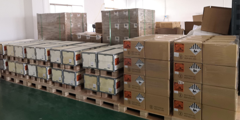
Li-ion batteries not only live longer when stored partially charged; they are also less volatile in shipment should an anomaly occur. The International Air Transport Association (IATA) and FAA mandate that all removable Li-ion packs be shipped at 30% state-of-charge. (More on BU-704a: Shipping Lithium-based Batteries by Air.) SoC can be estimated by measuring the open circuit voltage of a rested battery. (See also BU-903: How to Measure State-of-charge.)
Relating SoC to voltage can be inaccurate as the voltage curve of Li-ion between 20% to 100% charge is flat, as Figure 1 demonstrates. Temperature also plays a role, so do the active materials used in a cell. Aviation authorities seem less concerned about the exact 30% SoC but the importance of shipping Li-ion below 50% SoC. Larger misgivings are wrong labeling by passing Li-ion as a benign nickel-based chemistry.
To bring Li-ion to 30% SoC, discharge the battery in a device featuring a fuel gauge and terminate the discharge at 30% charge. The Embedded Battery Management System (BMS) does a reasonably good job giving SoC information but the measurements are seldom accurate. A full discharge to “Low Batt” is acceptable as long as the battery receives a charge at destination. Keeping Li-ion in a discharged state for a few months could slip the pack to sleep mode. (See BU-808a: How to Awaken a Sleeping Li-ion.)
Modern chargers feature the “AirShip” program that prepares a Li-ion pack for air shipment by discharging or charging the battery to 30% SoC on command. Typical methods are a full discharge with subsequent recharge to 30% using coulomb counting or advanced Kalman filters. Li-ion batteries built into devices have less stringent SoC requirements than removable packs.
Simple Guidelines for Storing Batteries
- Primary batteries store well. Alkaline and primary lithium batteries can be stored for 10 years with moderate loss capacity.
- When storing, remove the battery from the equipment and place in a dry and cool place.
- Avoid freezing. Batteries freeze more easily if kept in discharged state.
- Charge lead acid before storing and monitor the voltage or specific gravity frequently; apply a charge if below 2.07V/cell or if SG is below 1.225 (most starter batteries).
- Nickel-based batteries can be stored for 3–5years, even at zero voltage; prime before use.
- Lithium-ion must be stored in a charged state, ideally at 40 percent. This prevents the battery from dropping below 2.50V/cell, triggering sleep mode.
- Discard Li-ion if kept below 2.00/V/cell for more than a week. Also discard if the voltage does not recover normally after storage. (See BU-802b: What does Elevated Self-discharge do?)
| CAUTION |
When charging an SLA with over-voltage, current limiting must be applied to protect the battery. Always set the current limit to the lowest practical setting and observe the battery voltage and temperature during charge. In case of rupture, leaking electrolyte or any other cause of exposure to the electrolyte, flush with water immediately. If eye exposure occurs, flush with water for 15 minutes and consult a physician immediately.
Wear approved gloves when touching electrolyte, lead and cadmium. On exposure to skin, flush with water immediately. |