How to Charge an 18650 Battery Pack with a BMS: A Complete Guide
The 18650 lithium-ion battery pack is a cornerstone in modern electronics, powering everything from portable devices to high-performance electric vehicles. To maximize the lifespan and ensure the safety of these powerful cells, a Battery Management System (BMS) is indispensable. This comprehensive guide will walk you through the precise process of safely charging an 18650 battery pack equipped with a BMS, guaranteeing both optimal performance and extended longevity for your rechargeable lithium-ion batteries.
Understanding 18650 Battery Packs and BMS Functionality
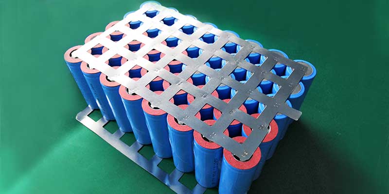
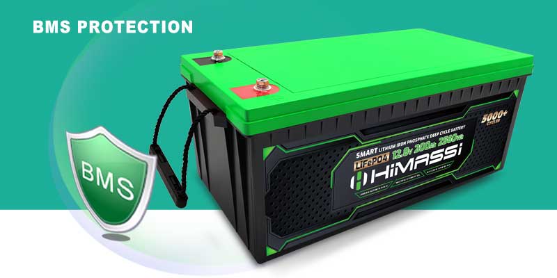
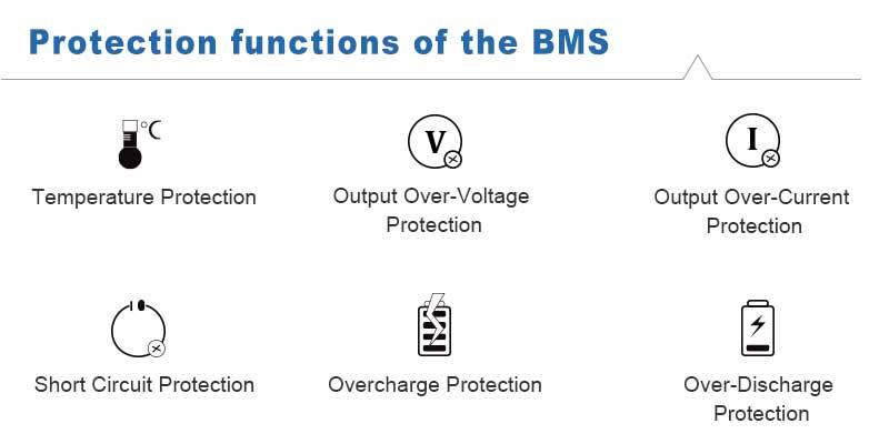
The “18650” designation refers to the cell’s dimensions: 18mm in diameter and 65mm in length. These Li-ion cells are highly sought after for their impressive energy density, high discharge rates, and robust durability. A BMS (Battery Management System) is a critical electronic circuit that acts as the guardian of your battery module, offering crucial protection against common hazards. These include overcharging protection, deep discharging prevention, overheating safeguards, and cell balancing, all of which are vital to prevent premature battery degradation or potentially hazardous situations. Understanding how to correctly power a battery pack and protect it with BMS circuitry is key.
Preparing Your 18650 Battery Pack for Charging
Before initiating the charging cycle, it is paramount to ensure that your BMS and custom battery pack are correctly configured and in perfect working order.
- Connection Integrity: Double-check all wire connections for security and any signs of wear or damage. Loose connections can lead to inefficient charging or safety risks.
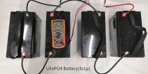
- BMS Compatibility: Verify that your chosen BMS is fully compatible with your specific battery pack voltage (e.g., 3S, 4S, 5S configurations) and the lithium-ion battery chemistry of your 18650 cells. Incompatibility can lead to serious issues.
- Charger Selection: Ensure you have a dedicated lithium-ion battery charger that matches the voltage and current requirements of your pack and BMS. Using an incorrect charger can damage the cells.
Step-by-Step 18650 BMS Charging Process
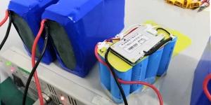
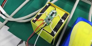
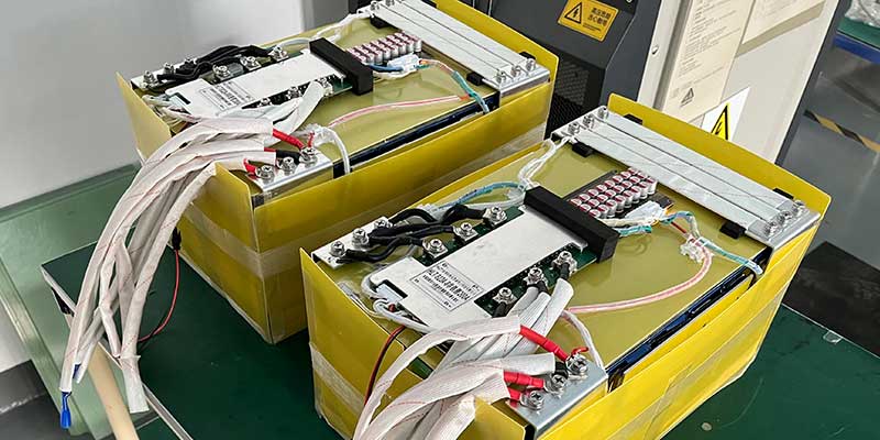
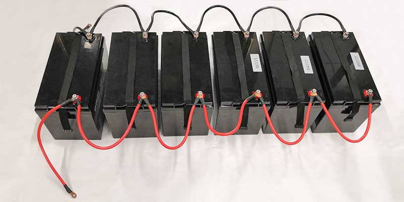
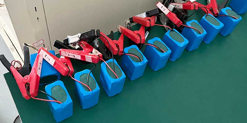
- Secure BMS-Battery Connection: Begin by ensuring your BMS is securely and correctly connected to your 18650 battery pack. Refer to your specific BMS wiring diagram or manual to confirm that the balance leads and main power connections between the individual cells and the BMS are accurate. This step is critical for proper cell balancing and overall battery health.
- Attach the Charger to the BMS: Connect your compatible battery charger directly to the input terminals of the BMS. Never connect the charger directly to the battery cells themselves, as this bypasses the essential protective functions of the BMS. Ensure the charger’s output voltage and current align with the specifications recommended for your specific battery configuration to avoid any potential damage.
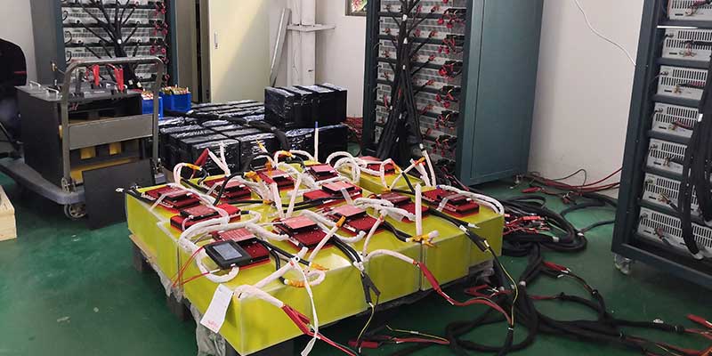
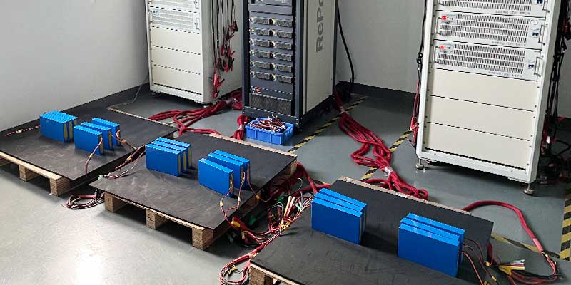
- Initiate Charging Cycle: Plug in your charger to the power source and initiate the charging process. The BMS will immediately begin to monitor the state of charge (SoC) for each individual cell within the pack. Its primary function during this phase is to ensure that all cells are charged evenly, actively preventing any single cell from experiencing overcharge stress.
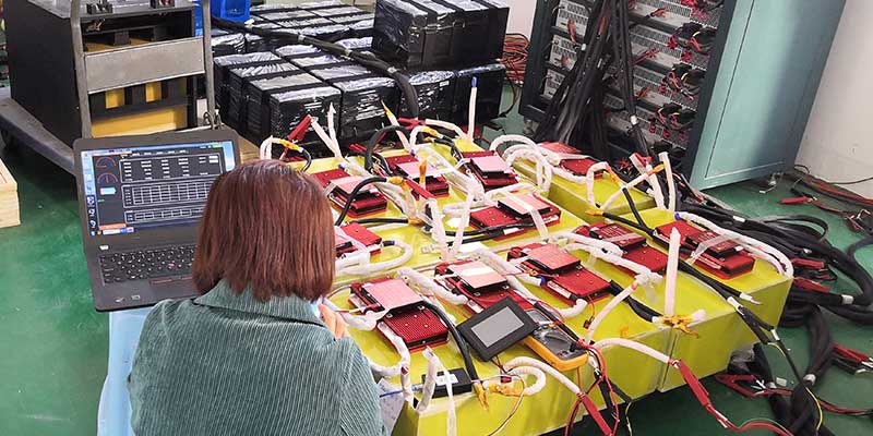
- Continuous Monitoring: Throughout the charging process, it is advisable to keep a close watch on the system. Many advanced BMS units feature built-in indicators (LEDs) or digital interfaces that display the real-time status of individual battery cells, including voltage and temperature. Monitoring these indicators will confirm that everything is charging as expected and that the BMS protection circuits are functioning.
- Charge Completion and Disconnection: Once the 18650 battery pack reaches its full charge capacity, the BMS will automatically terminate the charging process, preventing overvoltage conditions. At this point, safely disconnect the charger from the BMS, and then, if necessary for storage or maintenance, disconnect the BMS from the battery pack.
Safety Tips and Best Practices for Charging 18650 battery pack
Adhering to safety guidelines is paramount when working with high-power lithium batteries:
- Fire-Proof Charging Environment: Always charge your lithium-ion power pack in a non-flammable, fire-resistant area, such as on a concrete floor or in a dedicated Li-ion safe charging bag.
- Never Leave Unattended: Avoid leaving a charging battery pack unattended, especially during the initial stages. A fault can develop quickly.
- Regular Inspections: Periodically inspect your battery pack, individual 18650 cells, and the BMS for any signs of physical damage, swelling, leaks, or overheating.
- Flammable Material Avoidance: Keep the charging setup away from any flammable materials like curtains, paper, or wood.
- Proper Ventilation: Ensure adequate ventilation in the charging area to dissipate any heat buildup.
Troubleshooting Common 18650 Charging Issues
Should you encounter problems during the charging process, such as the BMS indicating a cell imbalance, abnormal temperatures, or a cell failing to charge, consider these steps:
- Connection Check: Re-verify all wiring connections between the cells, the BMS, and the charger. Loose or faulty connections are a frequent cause of issues.
- Component Integrity: Confirm that all components, including the charger, BMS, and individual cells, are functioning correctly and are not damaged.
- Manufacturer Documentation: Consult the specific manufacturer’s documentation for both your BMS and charger for detailed troubleshooting guides.
- Professional Assistance: If problems persist, it is highly recommended to seek professional assistance from a qualified electronics technician specializing in battery systems.
Why a BMS is Indispensable for 18650 Battery Packs
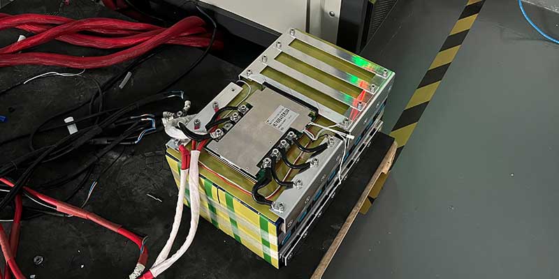
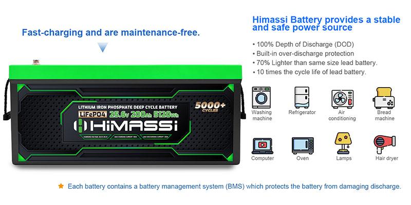
Utilizing a BMS is not merely a recommendation; it is an absolute necessity for both safety and optimal performance of your 18650 power source. It significantly extends the cycle life of your battery pack by ensuring precise voltage regulation, effective thermal management, and accurate current limiting. A properly functioning BMS can drastically reduce the risk of battery failure, which can range from reduced capacity to thermal runaway events. It ensures each battery cell operates within its safe parameters, maximizing the return on your battery investment.
About Himax Electronics: Advanced Battery Management Solutions
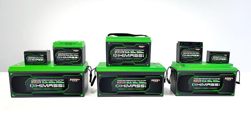
Himax Electronics stands at the forefront of advanced battery management solutions, offering cutting-edge BMS products engineered to significantly enhance both the safety and performance of lithium battery packs. With a steadfast commitment to innovation and unwavering customer satisfaction, Himax Electronics provides custom-tailored solutions that meticulously meet the specific needs of diverse projects, from DIY power walls to industrial battery applications.
Himax Electronics is dedicated to advancing battery technology through sophisticated BMS solutions that prioritize safety, reliability, and efficiency. For more detailed information about our comprehensive product range and how we can assist with your battery management system design or specific power pack requirements, we invite you to visit our website or contact our expert support team.