What is the Best LiFePO4 Battery? A Comprehensive Guide
LiFePO4 (Lithium Iron Phosphate) batteries have revolutionized power storage with their remarkable safety, longevity, and performance. Ideal for applications ranging from renewable energy storage to electric vehicles, these batteries offer numerous advantages over traditional lithium-ion counterparts. This guide explores the factors that make the best LiFePO4 battery and how Himax Electronics enhances these high-quality battery solutions.

Understanding LiFePO4 Batteries
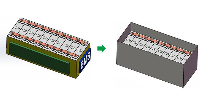
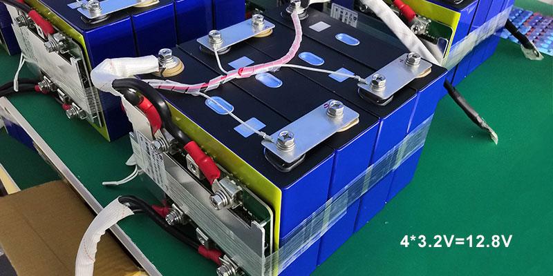
LiFePO4 batteries are known for their stable chemistry, which offers a lower risk of overheating and is less prone to thermal runaway. With a typical voltage of 3.2V per cell, these batteries provide a durable and safe alternative for high-demand applications. They are also known for a longer cycle life, often exceeding 2000 cycles at 80% depth of discharge (DoD), significantly more than other lithium-ion types.
Criteria for the Best LiFePO4 Battery
-
Energy Density: Top-quality LiFePO4 batteries have a high energy density, allowing for a lighter and smaller battery at the same capacity.
-
Cycle Life: One of the strongest points of LiFePO4 batteries is their cycle life. The best batteries offer upwards of 2000-5000 cycles at 80% DoD, making them an economical choice over the long term.
-
Safety: LiFePO4 is one of the safest lithium battery types available. The best batteries are built with robust safety features, including built-in protection against overcharging, deep discharge, and high temperature.
-
Performance: The best batteries maintain consistent performance even under varying environmental conditions. This includes retaining capacity at lower temperatures and delivering high currents without significant voltage drops.
-
Charging Speed: Top-rated LiFePO4 batteries support fast charging, which is essential for applications requiring quick turnaround times.
-
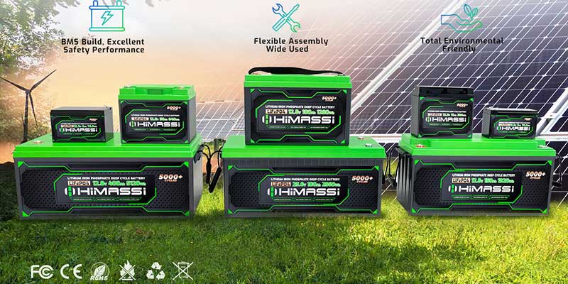
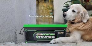
Environmental Impact: The best LiFePO4 batteries are constructed with eco-friendly materials and processes, minimizing the environmental footprint throughout their lifecycle.
Selecting the Right LiFePO4 Battery
-
Application-Specific Requirements: The choice of the best LiFePO4 battery often depends on its intended use. For instance, solar energy storage systems require batteries with excellent cycle life and capacity retention, while portable electronics demand compact and lightweight batteries.
-
Manufacturer Reputation: Choosing batteries from reputable manufacturers ensures reliability and service support. Quality manufacturers provide clear information about battery specifications, warranty terms, and customer support.
-
Certifications: Look for batteries that have relevant certifications, such as UL, CE, and RoHS, which indicate compliance with international safety and environmental standards.
Himax Electronics: Enhancing LiFePO4 Battery Solutions
Himax Electronics stands at the forefront of providing high-quality LiFePO4 battery solutions. Here’s how Himax makes a difference:
-
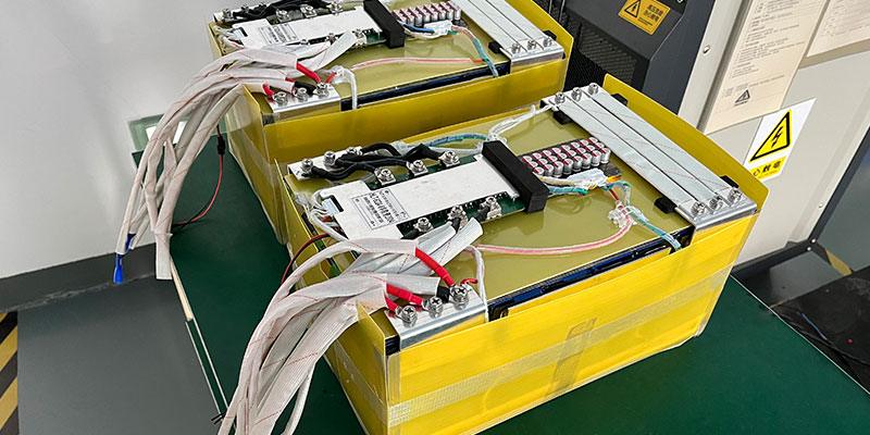
Advanced Technology: Himax employs cutting-edge technology in the design and manufacture of their batteries, ensuring top performance, durability, and safety.
-
Customization: Understanding that different applications have unique power requirements, Himax offers customized battery solutions tailored to specific needs, enhancing the overall efficiency and effectiveness of the battery system.
-
Sustainability Focus: Himax is committed to sustainable practices, using environmentally friendly materials and processes to minimize ecological impact.
-
Expert Support: With a team of experienced professionals, Himax provides excellent customer service, offering technical support and advice to help clients choose the best battery solutions for their needs.
Conclusion
Determining the best LiFePO4 battery depends on several factors including application, performance requirements, and manufacturer support. Himax Electronics provides top-tier LiFePO4 solutions that meet the highest standards of safety, performance, and sustainability. For anyone looking to integrate reliable and efficient battery technology into their systems, Himax offers the expertise and products to ensure success.
For more detailed information on selecting the right LiFePO4 battery or to consult with a battery expert, visit Himax Electronics’ website or contact their support team.