Introduction
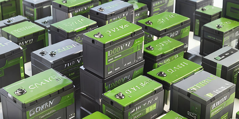
The European lithium-ion battery market is experiencing rapid growth amidst the global shift towards renewable energy and electric mobility. The demand for lithium batteries is being driven by sectors such as electric vehicles (EVs), renewable energy storage, and industrial applications. In 2024, the wholesale procurement of lithium batteries will face several emerging trends that will not only impact procurement strategies but also shape the overall market landscape. This article explores the top five key trends in lithium battery wholesale procurement in Europe for 2024.
Trend 1: The Push from Sustainability and Green Energy Policies
With European governments increasing their support for sustainable development, the procurement landscape for lithium batteries is evolving. The European Union’s Green Deal and carbon neutrality goals are driving the adoption of lithium batteries in renewable energy storage and electric mobility. Companies are prioritizing the procurement of batteries that meet environmental standards to comply with increasingly stringent carbon emission regulations. These policies are transforming the supply chain, making sustainable production a key competitive advantage for lithium battery suppliers.
The demand for renewable energy is also growing significantly, particularly in the wind and solar sectors. Lithium batteries are widely used in energy storage systems to ensure the stable supply of these renewable energy sources. This focus on sustainability is reshaping wholesale procurement strategies, with companies opting for suppliers that minimize carbon emissions throughout production and handling processes.
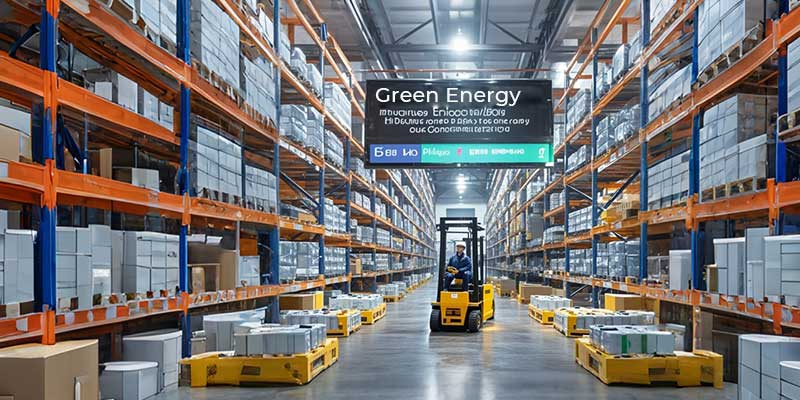
Trend 2: Supply Chain Diversification and Geopolitical Challenges
Geopolitical dynamics have had a major impact on the supply of raw materials for lithium batteries. In recent years, geopolitical uncertainty has increased the risk associated with the supply of critical raw materials such as lithium, cobalt, and nickel. To address these challenges, European lithium battery buyers are diversifying their supply chains to reduce dependence on a single country or region, especially reducing reliance on the Asian market.
This need for supply chain diversification has led companies to invest more in local suppliers, particularly in establishing more mining and battery production facilities within Europe. This not only helps stabilize supply but also reduces transportation costs and improves control over all stages of the supply chain. The complexity of geopolitical issues makes supply chain security and resilience central considerations in lithium battery wholesale procurement.
Trend 3: Growing Demand from Electric Vehicles (EVs)
The rapid expansion of the electric vehicle market is one of the primary drivers of increased lithium battery demand. European governments have introduced various incentives to promote EV adoption, such as purchase subsidies, tax breaks, and investments in charging infrastructure. These policies have directly contributed to increased EV sales, thus driving higher demand for lithium batteries.
For lithium battery wholesalers, the expanding EV market means a need to focus on characteristics such as high energy density, safety, and long cycle life. To meet the needs of EV manufacturers, battery suppliers must continuously improve product quality and maintain a competitive edge in wholesale procurement. Furthermore, as EV demand for lithium batteries grows, procurement priorities are shifting, particularly regarding requirements for performance and safety.
Trend 4: Price Volatility and Cost Control
Price volatility of key raw materials, such as lithium, cobalt, and nickel, has a direct impact on the production cost of lithium batteries. In recent years, due to geopolitical tensions and supply chain bottlenecks, the prices of these raw materials have fluctuated significantly. To cope with price uncertainty, many companies are choosing to secure long-term contracts to stabilize supply costs or invest in new mining and refining projects to reduce dependence on external suppliers.
Additionally, companies are investing more in technological innovation to lower production costs. For instance, improving battery manufacturing processes, optimizing material usage, and researching alternative materials to reduce dependence on expensive metals are all measures that can help companies achieve better cost control in lithium battery wholesale procurement, thereby maintaining market competitiveness.
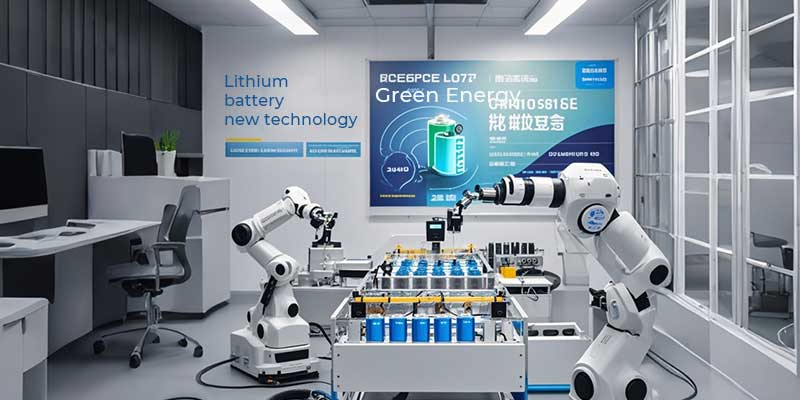
Trend 5: Emerging Technologies and Battery Recycling
Ongoing innovation in lithium battery technology is providing the market with more options. For example, solid-state batteries are considered the next-generation battery technology, with higher energy density and better safety features making them a focal point of industry attention. Although solid-state batteries have yet to be commercialized on a large scale, their technological advancements will significantly impact future procurement demands.
Meanwhile, battery recycling is becoming increasingly important in the European market. As lithium battery demand grows, effectively recycling and reusing spent batteries has become a critical issue. Battery recycling not only reduces dependence on raw materials but also mitigates environmental pollution, making it an essential factor for companies engaged in wholesale procurement. By establishing a robust recycling network, companies can reduce costs while achieving sustainability goals.
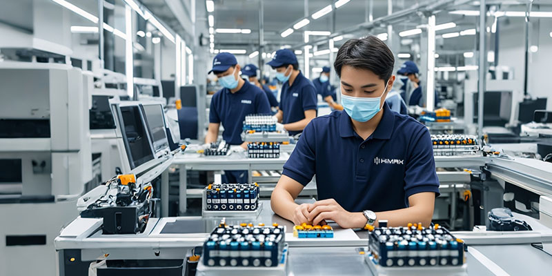
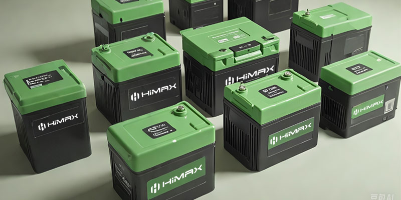
About Himax Electronics
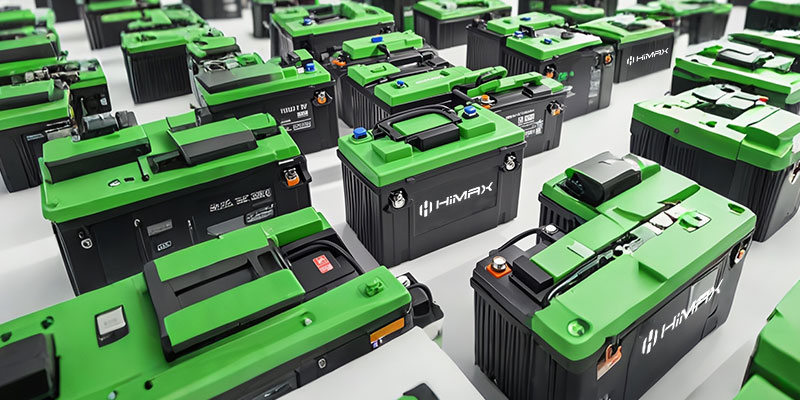
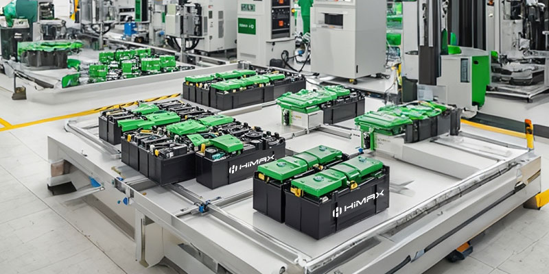
Himax Electronics, a leading supplier in the lithium battery industry, has established a strong presence in the European market through years of experience and technical expertise. We specialize in providing high-quality, customized lithium battery solutions to meet the needs of different applications. Whether for electric vehicles, renewable energy storage, or industrial use, Himax offers the most suitable products and services to our customers.
In light of the five key trends in lithium battery wholesale procurement for 2024, Himax Electronics remains at the forefront of the industry. By partnering with global suppliers, we ensure a diversified and stable supply chain. We are also committed to environmental sustainability, strictly adhering to green energy policies to provide products that meet environmental standards. Himax is actively investing in new technologies and battery recycling to help our customers stay ahead in an increasingly competitive market.
Conclusion
In 2024, the wholesale procurement of lithium batteries in Europe will be influenced by several key trends, including the push from sustainability policies, supply chain diversification, growing EV demand, raw material price volatility, and advancements in new technologies. These trends will not only shape the market landscape but also present new opportunities and challenges for companies. With its industry experience and commitment to innovation, Himax Electronics will continue to support customers in navigating these changes and achieving sustainable growth.