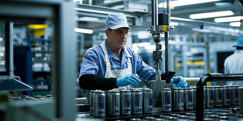
Scientists cook up a green recipe for recycling lithium-ion batteries using vegetable oil.
Research led by Professor Andy Abbott and Dr. Jake Yang at the University of Leicester working under the Faraday Institution’s ReLiB project found an innovative way of recovering valuable battery-grade metal oxides from crushed batteries by using nanoemulsions created from a trace of cooking oil in water. The study is published in the journal RSC Sustainability.
From everyday experience, we know oil and water do not mix unless we add soap, but research has shown that using ultrasound can create nano-droplets of oil that are stable for weeks. Crucially, oil nano-droplets are found to purify battery waste, commonly known as “black mass,” as it contains a mixture of carbon (graphite) and valuable lithium, nickel and cobalt metal oxides (NMC).
The oil nano-droplets stick to the surface of the carbon, acting as a “glue” to bind hydrophobic graphite particles together to form large oil-graphite conglomerates which float on water, leaving the valuable and hydrophilic lithium metal oxides untouched. The oil-graphite conglomerate can simply be skimmed off, leaving pure metal oxides.
Current recycling techniques use a combination of furnace heat treatment to burn off the undesired graphite, thereby increasing the CO2 footprint of the EV value chain, as well as concentrated corrosive acids which take valuable battery-grade metal oxides all the way back to the lower-valued battery precursor materials from which the battery was first made.
The Leicester-developed emulsion technique allows short-loop recycling of lithium-ion batteries. The battery-grade crystalline structure of the recovered material is not destroyed in this process and allows the remanufacturing of the recovered material directly back into new battery cells, unlike pyro/hydrometallurgical methods. This could potentially make the battery supply chain more sustainable and cheaper.
Dr. Jake Yang from the University of Leicester School of Chemistry said, “This quick, simple and inexpensive method could revolutionize how batteries are recycled at scale. We now hope to work with a variety of stakeholders to scale up this technology and create a circular economy for lithium-ion batteries.”
The Electric Revolution comes with drawbacks—one being challenges around how we efficiently and sustainably recycle large volumes of batteries at the end of their working life.
The use of batteries for electric vehicles and energy storage is only a sustainable future if the recycling pathway is green and cost-efficient. Globally, there are an estimated 40 million electric vehicles (EVs), and there are approximately 10 billion active mobile phones, laptops and tablets worldwide, all powered by lithium-ion batteries. However, the lack of regulations means lithium-ion battery packs are not designed to be recycled.
The Universities of Leicester and Birmingham are also collaborating to bring together several technologies developed under ReLiB in an InnovateUK project, ReBlend. This is creating a pilot line capable of processing 10s of kg/h of black mass to demonstrate that this short loop reprocessing can function economically to provide battery grade material for new cells.
“The ReLiB project is one of the Faraday Institution’s flagship projects developing innovative technology to capture value and retain scarce resources in the circular economy of battery manufacture and recycling. This work offers a promising route for short-loop recycling of lithium-ion batteries at scale,” commented Professor Martin Freer, CEO of the Faraday Institution.
More information: Chunhong Lei et al, Using ultrasonic oil–water nano-emulsions to purify lithium-ion battery black mass, RSC Sustainability (2025). DOI: 10.1039/D4SU00771A
https://himaxelectronics.com/wp-content/uploads/2025/01/Sustainable_Batteries.webp400800administrator/wp-content/uploads/2019/05/Himax-home-page-design-logo-z.pngadministrator2025-03-21 02:02:322025-03-21 02:12:22Scientists cook up a green recipe for recycling lithium-ion batteries using vegetable oil
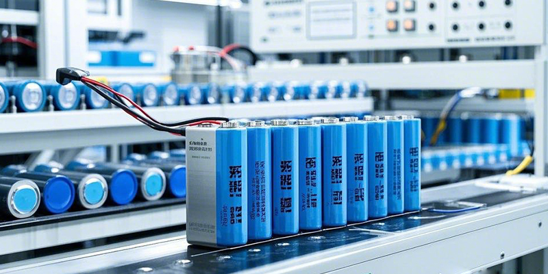
In modern electronic devices and power tools, lithium batteries have become an indispensable power source due to their high energy density, long cycle life, and lightweight properties. The 36V 15000mAh lithium battery, as a high-performance solution, is widely used in electric bicycles, energy storage systems, industrial equipment, and more. However, customizing a 36V 15000mAh lithium battery to meet specific requirements is no easy task—it requires full control over the process from design to production. This article provides a comprehensive guide to help you understand how to customize a 36V 15000mAh lithium battery and answers common questions.
Basic Characteristics of 18650 Battery Cells
Size and Specifications
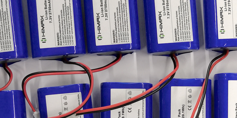
The 18650 battery cell is a standardized lithium-ion battery, named after its dimensions: 18mm in diameter and 65mm in length. This specification has become a mainstream choice in the lithium battery market due to its mature production process and wide range of applications.
Voltage and Capacity
A single 18650 battery cell has a standard voltage of 3.7V and a capacity typically ranging from 2000mAh to 3500mAh. By combining multiple cells in series and parallel, different voltage and capacity requirements can be achieved. For example, 10 cells in series can achieve 37V, while parallel connections can increase the total capacity.
Chemical Composition
The chemical composition of 18650 battery cells includes cathode materials (such as ternary lithium or lithium iron phosphate), anode materials (such as graphite), electrolytes, and separators. Different chemical formulations affect battery performance, including energy density, cycle life, and safety.
Advantages of 18650 Battery Cells in 7.4V 4400mAh Applications
The 18650 battery cell, with its standardized design, high performance, and mature production process, is an ideal solution for 7.4V 4400mAh lithium-ion batteries. Below, we analyze its advantages in terms of voltage matching, capacity optimization, and application scenarios.
Voltage Matching
A 7.4V voltage is typically achieved by connecting two 18650 battery cells in series. A single cell has a standard voltage of 3.7V, so two cells in series reach 7.4V. This combination is simple, efficient, and meets the needs of most portable devices.
Advantages of Series Design: Series design not only increases voltage but also maintains a reasonable size and weight for the battery pack. For example, two 18650 cells in series measure only 36mm in diameter and 65mm in length, making them ideal for space-constrained devices.
Voltage Stability: 18650 cells maintain stable voltage output during discharge, which is crucial for devices requiring constant voltage, such as power tools and drones.
Capacity Optimization
A 4400mAh capacity can be achieved in two ways:
1.Parallel Design: Using two 2200mAh cells in parallel achieves a total capacity of 4400mAh. Parallel design increases capacity without raising voltage, making it suitable for devices requiring long runtimes.
2.High-Capacity Cells: Directly using a single 4400mAh high-capacity 18650 cell. This simplifies battery pack design and reduces connection points and failure risks.
Advantages of Parallel Design: Parallel design not only increases capacity but also enhances discharge capability. For example, two 2200mAh cells in parallel can double the maximum discharge current, making them suitable for high-power devices.
Advantages of High-Capacity Cells: High-capacity cells reduce the size and weight of the battery pack while lowering assembly complexity, making them ideal for applications with strict space and weight requirements.
Application Scenarios
The 7.4V 4400mAh battery pack, with its high performance and flexibility, is widely used in various fields:
Drones:
Requirements: Drones need high-energy-density batteries to extend flight time while requiring lightweight and compact designs.
Solution: The 7.4V 4400mAh battery pack provides sufficient energy support while maintaining a lightweight design, meeting the endurance and performance needs of drones.
Power Tools:
Requirements: Power tools require stable voltage output and high discharge capability to support high-power operation.
Solution: The 7.4V 4400mAh battery pack delivers stable voltage and high discharge current, ensuring efficient operation of power tools.
Portable Medical Devices:
Requirements: Portable medical devices need long-lasting batteries that are also safe and reliable.
Solution: The 7.4V 4400mAh battery pack offers extended runtime and ensures safety through built-in protection circuits.
Other Applications:
Outdoor Lighting: The 7.4V 4400mAh battery pack provides long-lasting power for outdoor lighting equipment.
Portable Audio: High-capacity battery packs extend the playback time of audio devices, enhancing user experience.
Future Trends of 18650 Battery Cells
Technological Innovations
With advancements in material science, 18650 battery cells are moving toward higher energy density, longer cycle life, and faster charging speeds. For example, silicon-carbon anode materials can significantly increase capacity, while solid-state electrolytes may improve safety.
Market Demand
As power tools, energy storage systems, and electric vehicles become more popular, the demand for high-performance lithium batteries continues to grow. The 7.4V 4400mAh battery pack, with its balanced performance and cost, is a preferred choice for many applications.
Alternative Technologies
Although 18650 cells currently dominate the market, emerging technologies like solid-state batteries may pose challenges in the future. Solid-state batteries offer higher safety and energy density, but their cost and production processes still need optimization.
The 18650 battery cell, with its standardized design, high performance, and mature production process, is an ideal solution for 7.4V 4400mAh lithium-ion batteries. Through series and parallel configurations, it can flexibly meet the voltage and capacity requirements of various devices. In the future, with continuous technological innovation and growing market demand, 18650 battery cells will continue to play a vital role in the high-performance battery industry.
If you need to customize a 36V 15000mAh lithium battery or other high-performance battery solutions, contact HIMAX Electronics. We offer end-to-end services from design to production, ensuring the highest quality products and technical support. Reach out to us today for more information or a quote!
https://himaxelectronics.com/wp-content/uploads/2025/03/7.4V-4400mah-lithium-ion-battery.webp400800administrator2/wp-content/uploads/2019/05/Himax-home-page-design-logo-z.pngadministrator22025-03-21 01:58:382025-03-21 02:06:23Why is the 18650 battery cell a 7.4V 4400mAh high-performance lithium-ion battery solution?
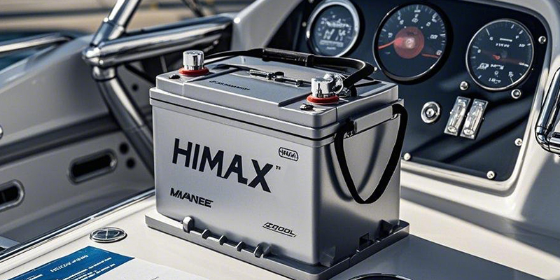
In the demanding marine environment, reliable batteries are the lifeline of vessels—powering navigation systems, emergency lighting, and engine startups. For bulk buyers, choosing the right supplier is critical. Himax, with 20+ years of expertise in marine lithium batteries, delivers unmatched performance, cost efficiency, and compliance for commercial fleets, yacht builders, and offshore operations.
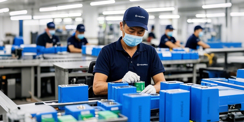
Himax Manufacturing: Engineering Excellence Since 2003
R&D Leadership: Rigorous tests validate every battery’s reliability.
Strict quality control system: Production visualization data to monitor the pass rate of each process, 100% quality inspection to provide test data for Himax’s customers..
Global Compliance: UL, CE, UN38.3, and RoHS certifications guaranteed for hassle-free shipping.
Technical Showdown: Himax Lithium vs. Lead-Acid Batteries
We’ve created a detailed comparison table to help bulk buyers make informed decisions:
The table above highlights Himax’s 3,000-cycle durability—6x longer than premium AGM batteries.
Real-World Impact:
A 50-vessel yacht operator reduced battery replacements from 3 times/year to once/decade.
10-year TCO savings: $1.2M per 100 boats (Download TCO Calculator).
4x Faster Charging, Zero Downtime
Metric
Before Himax
After Himax
Charging Time
4 hours
55 minutes
Daily Departures
4 rounds
7 rounds
Annual Revenue Increase
—
+$280,000
Technical Support: Himax’s proprietary thermal management system prevents overheating during rapid charging, ensuring battery health even after 2,500+ cycles.
Double the Power, Half the Weight
Peak Output: 5C discharge rate supports heavy winches and sonar systems.
Arctic-Ready: Operates at -20°C with patented low-temperature electrolytes.
Quality Assurance: Built for Global Waters
Military-Grade Testing: Vibration, salt spray, and IP67 waterproof validation.
Traceability: Laser-etched QR codes track every cell from raw materials to delivery.
Certifications: UL 1973 (marine), IEC 62619, and DNV-GL compliance.
Bulk Buyer Benefits: Customization & Savings
OEM/ODM Services:
Custom sizes (e.g., 48V 100Ah for yacht).
Branded battery management systems (BMS) with real-time monitoring.
Himax Guarantee
Smart BMS Integration: Real-time monitoring via Bluetooth/app (voltage/temperature alerts).
Voltage options: 12V-72V (compatible with hybrid systems)
Safety Guaranteed: Explosion-proof design passes UN 38.3 nail penetration tests.
Success Story: A Norwegian fishing fleet cut fuel costs by 18% using Himax hybrid power systems.
Power Your Fleet Smarter
For bulk buyers, Himax marine lithium batteries offer:
Lower TCO: Save 40%+ versus lead-acid over 10 years.
Future-Proof Tech: Ready for smart shipping and automation trends.
https://himaxelectronics.com/wp-content/uploads/2025/03/custom_marine_lithium_batteries.webp400800administrator2/wp-content/uploads/2019/05/Himax-home-page-design-logo-z.pngadministrator22025-03-19 13:55:582025-03-19 13:55:58Bulk marine battery solutions, why more and more customers choose Himax
9V batteries power critical devices in both daily life and professional settings—from smoke alarms to precision multimeters. Yet consumers often face a dilemma: Should they choose affordable alkaline batteries or invest in lithium-ion rechargeables? This guide breaks down the science, performance, and economics of both options. As a leader in 9V lithium-ion innovation, HIMAX Electronics offers advanced solutions that redefine reliability and sustainability.
What Is a 9V Battery?
Design & Compatibility
With standardized dimensions (48.5mm × 26.5mm × 17.5mm), 9V batteries are universally compatible with devices requiring compact, high-voltage power. Their rectangular shape and snap-on terminals ensure easy installation.
Key Applications
· Smoke Alarms: Alkaline batteries last 1–2 years.
· Multimeters: Precision instruments demand stable voltage (alkaline or lithium).
· Wireless Microphones: Consistent power ensures uninterrupted audio.
· Portable Radios: Reliable for outdoor adventures.
· Voltage Curve: Starts at 9.5V–9.6V but gradually drops to 6V.
· Capacity: 400mAh–600mAh (varies by brand).
· Lifespan: Lasts hours to 2 years, depending on device usage.
Limitations
· Temperature Sensitivity: Struggles in extreme heat/cold.
· Disposable Design: Single-use creates recurring costs and environmental waste.
Cost Analysis
· Affordable upfront (2–2–5 per unit) but expensive long-term for high-drain devices.
· Recycling required: Mercury-free but contributes to landfill pollution if not recycled.
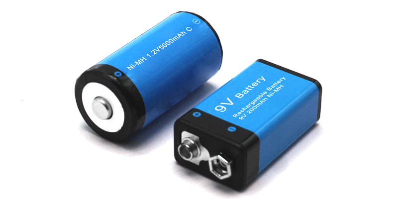
9V Lithium-Ion Rechargeable Batteries: Power Redefined
Advanced Chemistry
· Structure: Lithium compound cathode, graphite anode, and high-efficiency electrolyte.
· Voltage Stability: Maintains 9.9V–10V when fully charged, only dropping to 6.5V at depletion.
Unmatched Performance
· Capacity: 600mAh–2,000mAh (3–5x higher than alkaline).
· Lifespan: 300–1,000 recharge cycles (5–10 years with proper care).
· Efficiency: Low self-discharge (retains 80% charge after 1 year of storage).
· Durability: Operates flawlessly in -20°C to 60°C environments.
Economic & Environmental Edge
· Higher initial cost (15–15–30) but saves 70%+ over time versus disposables.
· Eco-friendly: Reusability reduces landfill waste by 90%.
Why Choose Himax 9V Lithium-Ion Batteries?
As a pioneer in battery tech, Himax delivers:
Ultra-High Energy Density: 1,200mAh+ capacity for extended runtime.
Smart Safety Protections: Built-in safeguards against overcharge, over-discharge, and short circuits.
All-Weather Reliability: Perfect for industrial tools, outdoor gear, and emergency devices.
Custom Solutions: OEM/ODM support for bulk orders and specialized applications (e.g., medical equipment).
Alkaline vs. Lithium-Ion: Which Should You Buy?
Pick Alkaline If:
O You need short-term, low-cost power for devices like wall clocks.
O The device drains batteries slowly (e.g., smoke detectors).
Choose Lithium-Ion If:
O You prioritize long-term savings (e.g., daily-use multimeters).
O Sustainability matters (fewer batteries in landfills).
O Your device operates in extreme temperatures.
Pro Tip: For smoke alarms, lithium-ion batteries last 3–5 years and provide stable voltage, reducing false alarms.
While alkaline 9V batteries work for occasional use, lithium-ion rechargeables are the smarter choice for performance, economy, and eco-consciousness. Himax 9V lithium-ion batteries stand out with military-grade durability, safety certifications, and tailored power solutions.
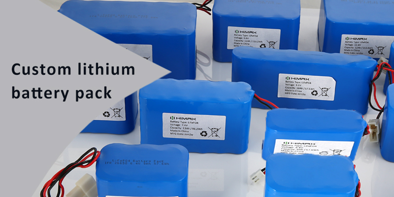
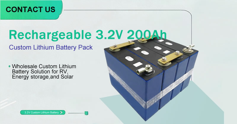
As technology continues to advance, the demand for tailored power solutions across various devices is growing rapidly. Standard battery products often fall short of meeting the high-performance needs of certain industries, prompting more businesses to opt for custom lithium-ion batteries to optimize device performance and extend battery life.
The 36V 15000mAh lithium battery, known for its high energy density, long lifespan, and stable discharge performance, is widely used in applications such as power tools, energy storage systems, electric bicycles, medical devices, and industrial automation equipment. Compared to traditional lead-acid batteries or off-the-shelf lithium batteries, customized solutions can better align with the specific technical requirements of different devices, ultimately boosting overall efficiency.
So, how do you go about customizing a 36V 15000mAh lithium battery? This article provides a comprehensive guide covering key parameters, the design process, production standards, and more, helping you choose the best battery solution for your needs.
Key Parameters for Customizing a 36V 15000mAh Lithium Battery
Before embarking on battery customization, it’s critical to define your product’s technical requirements to ensure the battery meets the device’s power demands and performs reliably in various environments.
Voltage and Capacity Requirements
36V: Ideal for high-power devices, ensuring consistent and stable output.
15000mAh: High-capacity design extends device runtime and reduces charging frequency.
Cell Type Selection
18650 or 21700 Cylindrical Cells: Suitable for devices requiring high energy density and stable discharge performance.
Polymer Pouch Cells: Offer a lighter, more flexible structure, perfect for devices with specific shape constraints.
BMS (Battery Management System) Configuration
Protects the battery from overcharging, over-discharging, overcurrent, and short circuits, enhancing safety.
Advanced smart BMS options can include Bluetooth monitoring, temperature control, and cell balancing, optimizing battery lifespan.
Housing and Encapsulation Options
ABS Plastic Housing: Cost-effective and impact-resistant.
Aluminum Alloy Housing: Excellent heat dissipation, ideal for high-load devices.
IP67 Protection Design: Enhances water and dust resistance, suitable for outdoor or specialized industrial environments.
Charge/Discharge Performance and Safety Standards
Must offer stable discharge rates to support devices with varying power needs.
Should comply with international safety certifications such as UL, CE, RoHS, and UN38.3 to meet global market standards.
The Customization Process: A Step-by-Step Breakdown from Concept to Completion
Needs Analysis and Design
Determine the device’s power requirements and calculate the optimal battery parameters.
Factor in usage scenarios to finalize battery size, encapsulation method, protection features, and other customization details.
Material Selection and Prototype Testing
Choose high-quality cell suppliers to ensure battery consistency and safety.
After prototype production, conduct tests including capacity, charge/discharge cycling, temperature rise, and short-circuit testing.
Mass Production and Quality Control
Utilize automated production processes to minimize human error and improve consistency.
Implement a rigorous quality management system during production, conducting multiple tests (voltage, current, temperature, internal resistance, etc.) to ensure product reliability.
Delivery and After-Sales Support
Use professional packaging to prevent damage during transportation.
Provide warranty and technical support to ensure customers can use the custom battery safely and effectively.
How to Choose the Right Lithium Battery Customization Supplier?
When customizing lithium-ion batteries, selecting an experienced supplier with reliable production capabilities is crucial. Below are key criteria to consider when evaluating potential suppliers:
Production Capacity Assessment
Do they have a complete production line, including cell encapsulation, BMS design, and assembly testing?
Are they ISO 9001 certified, ensuring their production processes meet international standards?
Supplier’s Technical Expertise
Do they have extensive industry experience and the ability to provide efficient, customized solutions?
Can they offer case studies or examples that demonstrate their technical capabilities and market reputation?
Delivery Timelines and Cost Management
Is their delivery timeline reasonable? Can they provide rapid prototyping?
Are their prices competitive in the market? How do they balance cost and quality?
Why Choose HIMAX Electronics?
As a trusted leader in the lithium battery industry, HIMAX Electronics brings years of expertise in delivering customized battery solutions, including high-quality 36V 15000mAh lithium batteries tailored to your specific needs. Our advantages include:
Premium Cell Selection: Ensuring battery stability and reliability.
Rigorous Quality Control: Compliant with UL, CE, RoHS, and other international certifications.
Fast Delivery and Excellent After-Sales Support: Ensuring the best possible customer experience.
If you’re looking for professional lithium-ion battery customization services, feel free to reach out to us. Our expert team is ready to provide you with the best solution for your needs!
https://himaxelectronics.com/wp-content/uploads/2025/03/custom-lithium-ion-battery_.webp400800administrator2/wp-content/uploads/2019/05/Himax-home-page-design-logo-z.pngadministrator22025-03-17 14:06:582025-03-17 14:06:58How to Customize a 36V 15000mAh Lithium Battery: A Complete Guide from Design to Production
A world-first technology has been developed by introducing a roll-to-roll compatible flash process into secondary battery electrode manufacturing, significantly suppressing the performance degradation of thick electrodes.
The research is published in the journal Small Methods. The findings present a new possibility of reducing battery costs by minimizing inactive materials and simplifying the manufacturing process while increasing energy density and capacity, making batteries smaller and lighter.
The Korea Institute of Machinery and Materials (KIMM) has developed an electrode activation technology utilizing an ultra-fast, large-area flash process to mitigate thick electrode degradation. Using the pilot-scale test bed, its compatibility with roll-to-roll (R2R) processes was successfully demonstrated.
Thick electrodes offer advantages such as high energy density, fewer battery pack layers, a simplified structure, and increased manufacturing efficiency, leading to a drastic reduction in production costs.
However, thick electrodes also face challenges, including increased resistance to lithium-ion and electron transport and limited electrolyte penetration, which lead to decreased overall electrochemical performance such as rate capability.
To address these issues, the research team introduced a flashlight irradiation process on thick electrodes for an instantaneous duration of less than one millisecond. The photothermal reaction triggered by this process instantly induces changes such as binder carbonization, interlayer expansion of active material (graphite), increased porosity, and an enlarged electrode-electrolyte interfacial area.
These chemical and structural modifications enhance lithium-ion and electron transport while improving electrolyte penetration, ultimately suppressing the performance degradation of thick electrodes.
By utilizing surface photothermal reactions, this technology prevents the entire thick electrode, including the current collector, from prolonged high-temperature exposure. This minimizes binder decomposition, preserving mechanical durability while also preventing oxidation-related thermal damage to the current collector.
This technology is highly compatible with standard roll-to-roll manufacturing processes and is expected to be expandable to various electrode materials, including nickel-cobalt-manganese (NCM) cathodes.
Furthermore, the research team of KIMM is applying and evaluating the flash process in the electrode drying stage. It has been confirmed that the technology can significantly reduce the energy consumption and processing time required for electrode drying while simultaneously inducing electrode activation effects.
Recently, in collaboration with lithium-ion battery equipment manufacturers, the team has been developing mass-production-scale facilities and conducting process evaluations.
The principal researcher, Dr. Kyoohee Woo of KIMM stated that since flash-based electrode activation technology is a post-treatment process compatible with roll-to-roll manufacturing, it can be easily integrated into existing production lines and facilities.
Moving forward, the team aims to enhance the technology’s maturity and continue testing and validation to facilitate its adoption by domestic lithium-ion battery manufacturers.
More information: Su Hyun Choi et al, Flashlight‐induced Ultrafast, Scalable Surface Activation of Highly Loaded Graphite Composite Anode, Small Methods (2024). DOI: 10.1002/smtd.202401361
https://himaxelectronics.com/wp-content/uploads/2025/03/U.S._vs._China_battery_industry.webp400800administrator/wp-content/uploads/2019/05/Himax-home-page-design-logo-z.pngadministrator2025-03-17 10:09:402025-03-17 10:10:43Enhancing lithium-ion battery performance with roll-to-roll compatible flash process technology
Electric vehicles (EVs) are revolutionizing the way we get around, but did you know that the heart of these vehicles—lithium-ion batteries—is heavily reliant on China’s supply chain? According to BloombergNEF, China currently dominates 77% of global EV battery production capacity, while the U.S. lags behind at just 14%. This dependency not only poses risks to supply chain security but could also drive up EV prices and hinder market competitiveness. Breaking free from China’s grip has become a critical step for U.S. electric vehicle battery production, and HIMAX Electronics is playing a pivotal role by offering high-performance battery solutions. In this article, we’ll dive deep into the state of battery manufacturing, the importance of reducing reliance on China, and how to choose the right battery supplier to add value to your business.
The Current State of the U.S. EV Battery Supply Chain: Why Are We So Dependent on China?
China’s battery manufacturing capacity reigns supreme globally, thanks to its economies of scale, control over raw materials, and low-cost production capabilities. According to the latest 2025 data, China produces 90% of the world’s graphite—a key raw material for lithium-ion battery anodes—and boasts over 300 gigawatt-hours of battery production capacity. This dominance leaves U.S. EV manufacturers heavily reliant on China, especially for lithium-ion battery production. Whether it’s Tesla, General Motors, or Ford, parts of these iconic brands’ battery components inevitably come from Chinese supply chains.
However, this dependency comes with significant risks. First, supply chain disruptions could lead to battery shortages, directly inflating EV prices. For instance, geopolitical tensions in 2022 caused fluctuations in battery raw material prices, impacting the stability of the U.S. EV market. Second, relying on China may stifle U.S. innovation and competitiveness, particularly in cutting-edge battery technologies. Geopolitical uncertainties further compound the issue—trade restrictions or export bans could leave U.S. EV manufacturers scrambling to secure batteries. Breaking free from China’s grip isn’t just about supply chain security; it’s about securing the future of the U.S. EV industry.
How to Break Free from China’s Grip: The Rise of U.S. Battery Manufacturing
To reduce dependence on China, the U.S. government has rolled out a series of supportive policies, with the Inflation Reduction Act (IRA) being the most significant. This legislation provides over $37 billion in tax credits and subsidies for U.S. electric vehicle battery production, incentivizing companies to build factories on American soil. As of 2025, the U.S. has announced plans for over 1,000 gigawatt-hours of battery production capacity, enough to meet EV demand through 2030. Examples include Tesla’s Gigafactory in Nevada, General Motors’ battery plant in Michigan, and Ford’s battery project in Kentucky—all of which have benefited from these policies. These initiatives not only lower production costs but also attract substantial investments, injecting fresh momentum into U.S. electric vehicle battery production.
Beyond policy support, the U.S. is showcasing strong potential in battery technology innovation. For example, American companies are accelerating the development of solid-state batteries, which promise higher energy density and longer lifespans compared to traditional lithium-ion batteries. HIMAX Electronics, a leader in battery technology, is contributing to this effort with its high-performance battery solutions, giving U.S. EV manufacturers a competitive edge. Our battery products not only enhance EV range but also reduce long-term maintenance costs, helping the U.S. secure a foothold in the high-end market. Additionally, HIMAX has made breakthroughs in battery recycling technology, repurposing battery materials to reduce reliance on imported raw materials and further bolstering the sustainability of U.S. electric vehicle battery production.
Localized production is a critical step in breaking free from China’s grip. By building a complete battery supply chain in the U.S., companies can significantly reduce the risk of supply chain disruptions while improving delivery efficiency. According to the Environmental Defense Fund, the IRA is expected to create 179,000 direct jobs and 800,000 indirect jobs, spanning battery manufacturing, raw material processing, and equipment maintenance. Localized production also shortens logistics timelines and cuts transportation costs, enabling EV manufacturers to offer more competitive prices.
How HIMAX Electronics Supports U.S. Battery Manufacturing
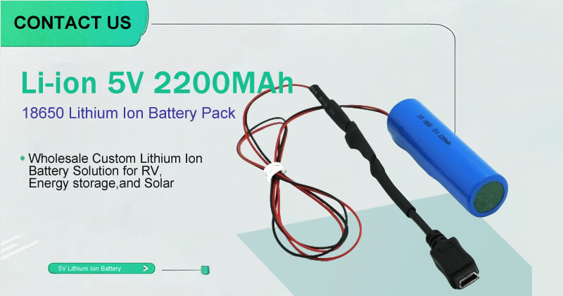
HIMAX Electronics is committed to providing high-performance battery solutions for U.S. electric vehicle battery production. Our battery products leverage advanced lithium-ion battery technology, offering high energy density, long lifespans, and fast charging capabilities. Whether used in passenger EVs or commercial vehicles, HIMAX batteries significantly enhance vehicle performance while lowering operating costs. For example, our battery products perform exceptionally well in extreme temperatures, ensuring EVs operate reliably in the frigid northern U.S. or the scorching southern states. Whether you’re an EV manufacturer or a distributor, HIMAX can provide the ideal lithium-ion battery solutions tailored to your needs.
How to Choose the Right EV Battery Supplier
When selecting an EV battery supplier, the following key factors are worth considering:
Performance: Does the battery’s energy density, cycle life, and charging speed meet your needs? High-performance lithium-ion batteries can significantly boost EV range and user experience.
Supply Chain Stability: Can the supplier offer localized production to reduce supply chain risks? In U.S. electric vehicle battery production, localized suppliers provide faster delivery and lower logistics costs.
Price: Does the battery offer good value for your budget? While localized production may involve higher initial costs, it can reduce supply chain risks and operating costs in the long run.
Technical Support: Does the supplier provide customized services and technical support? During EV development, expert technical support can help you bring new models to market faster.
Breaking free from China’s grip is a critical step for U.S. electric vehicle battery production, and this process is gaining momentum through policy support, technological innovation, and localized production. HIMAX Electronics, as a leader in battery technology, is dedicated to providing high-performance lithium-ion battery solutions for the U.S. EV industry, helping businesses enhance supply chain security, reduce costs, and boost market competitiveness. If you’re looking for a reliable battery supplier, consider partnering with HIMAX Electronics to drive the future of the U.S. EV industry.
https://himaxelectronics.com/wp-content/uploads/2025/03/domestic_battery_supply_chain.webp400800administrator2/wp-content/uploads/2019/05/Himax-home-page-design-logo-z.pngadministrator22025-03-15 12:03:552025-03-15 12:03:55U.S. Electric Vehicle Battery Manufacturing: A Critical Step Toward Breaking Free from China’s Grip?
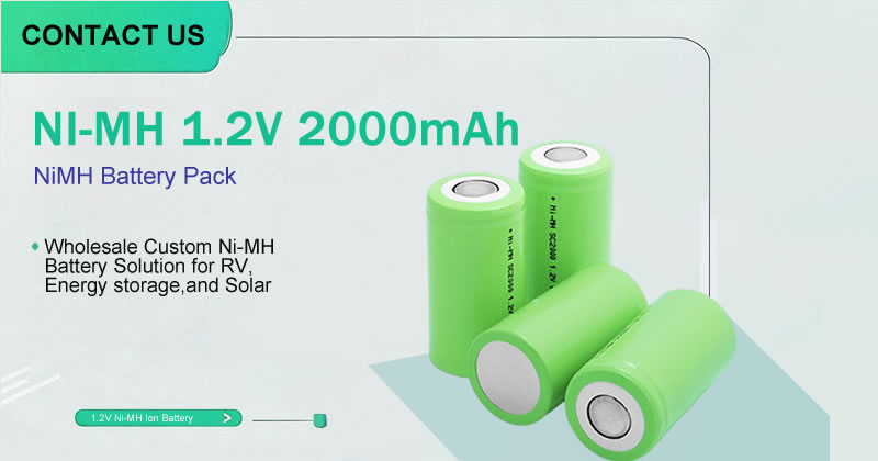
The Complexity and Importance of NiMH Battery Compliance
Amid the global push for energy transition and sustainability, nickel-metal hydride (NiMH) batteries have become essential energy solutions across industries, powering everything from industrial equipment and medical devices to consumer electronics, thanks to their high energy density and eco-friendly properties. However, for bulk buyers, ensuring that NiMH batteries meet international and regional regulatory standards is no easy feat. From the European Union’s RoHS and REACH regulations to the U.S.’s UN38.3 transportation safety certification and EPA environmental requirements, NiMH battery compliance involves a series of complex and time-consuming processes. These certification challenges not only increase time costs for buyers but can also significantly impact supply chain stability and market competitiveness.
So, how can bulk buyers efficiently navigate these intricate compliance requirements? And how does HIMAX Electronics, a leader in the battery industry, help optimize this challenge? This article will unlock the answers, guiding you to streamline your journey toward NiMH battery compliance. Learn more about practical NiMH battery compliance solutions.
The Current State of NiMH Battery Compliance: Pain Points for Bulk Buyers
In today’s globalized market, NiMH battery compliance has become a critical issue that bulk buyers must address. Below are the most common pain points buyers face during the compliance certification process:
Compliance requirements for NiMH batteries vary significantly across markets. For instance, the EU’s RoHS (Restriction of Hazardous Substances) directive strictly limits the presence of harmful substances like lead, mercury, and cadmium in batteries, while the U.S.’s UN38.3 transportation safety certification mandates rigorous safety standards during transit. This diversity in regulations means bulk buyers must tailor compliance strategies to each market, adding layers of complexity to the certification process.
Bulk buyers need assurance that the battery materials provided by suppliers meet regulatory standards, but the complexity of supply chains often makes tracing raw materials a daunting task. This challenge is especially pronounced when supply chains span multiple countries and regions, requiring buyers to invest significant time and resources to verify compliance at every step.
The compliance certification process typically involves multiple tests, documentation preparation, and third-party audits, driving up direct costs for buyers and risking project delays. For example, one company faced supply chain disruptions due to delays in completing UN38.3 transportation safety certification, resulting in missed market delivery deadlines and eroded customer trust.
These pain points make NiMH battery compliance a significant challenge for bulk buyers. Click to learn more about NiMH battery compliance solutions.
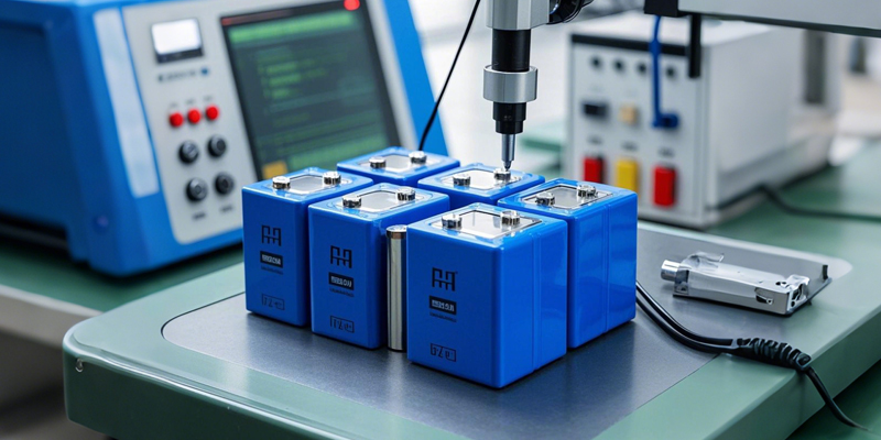
HIMAX Electronics’ Solutions: Innovative Practices to Optimize Compliance Certification
In the face of complex NiMH battery compliance challenges, HIMAX Electronics leverages its expertise and innovative practices to provide bulk buyers with a one-stop solution. Here’s how HIMAX optimizes the certification process:
HIMAX is committed to delivering NiMH battery products that meet international standards, with all products pre-certified under RoHS, REACH, UN38.3, and other key regulations. This means bulk buyers choosing HIMAX as their supplier can significantly reduce their own certification burden. HIMAX also provides detailed compliance documentation, including Material Safety Data Sheets (MSDS), test reports, and certification certificates, ensuring buyers can quickly meet the regulatory demands of their target markets.
HIMAX recognizes the critical role of supply chain transparency in achieving NiMH battery compliance. To this end, the company has implemented stringent supply chain management protocols, ensuring all raw material sources meet regulatory standards and providing fully traceable supply chain data. This transparency not only reduces compliance risks for buyers but also enhances overall supply chain efficiency.
To address the diverse needs of bulk buyers, HIMAX offers tailored compliance solutions. For example, if a buyer’s target market is the EU, HIMAX can provide products and documentation that meet RoHS and REACH requirements; if the target market is the U.S., HIMAX prioritizes support for UN38.3 transportation safety certification. This flexible service model ensures buyers can efficiently navigate the regulatory requirements of different markets.
Time is one of the most valuable resources for bulk buyers during the certification process. HIMAX’s expert team can assist buyers in completing compliance tests and certifications in a short timeframe, significantly reducing project timelines. For instance, one company, with HIMAX’s support, successfully completed RoHS certification for the EU market in just three months, saving 30% on certification costs.
Through these innovative practices, HIMAX not only streamlines the NiMH battery compliance certification process but also helps bulk buyers boost their market competitiveness. Learn more about innovative NiMH battery compliance solutions.
Key Regulations Explained: Compliance Requirements Bulk Buyers Need to Know
To help bulk buyers better tackle NiMH battery compliance challenges, here’s an overview of several key regulations. These are critical for buyers to understand when selecting suppliers and preparing compliance documentation:
RoHS is a mandatory EU regulation aimed at limiting the use of hazardous substances like lead, mercury, and cadmium in electronic products. For NiMH batteries, RoHS requires that the levels of these substances stay below specified thresholds. Bulk buyers entering the EU market must ensure their suppliers provide RoHS-compliant batteries and relevant test reports.
REACH is another critical EU regulation that mandates the disclosure of chemical substances in batteries, particularly Substances of Very High Concern (SVHC). For bulk buyers, choosing a supplier like HIMAX that has completed REACH registration can significantly reduce compliance risks.
UN38.3 is a global transportation safety certification standard that requires NiMH batteries to pass tests for vibration, shock, high temperature, and more during transit. This is a must-meet requirement for bulk buyers entering international markets. HIMAX’s NiMH battery products are all UN38.3-certified, ensuring buyers can seamlessly complete global transportation.
In the U.S., EPA regulations cover battery waste management and recycling requirements. Bulk buyers must ensure their suppliers’ battery products meet EPA environmental standards and provide proof of recyclability. Through sustainable production processes, HIMAX helps buyers meet EPA requirements.
Understanding these regulations is the first step toward NiMH battery compliance. Click to learn more about key NiMH battery compliance regulations.
Action Guide for Businesses: How to Efficiently Address NiMH Battery Compliance Challenges
To help bulk buyers efficiently tackle NiMH battery compliance challenges, here’s a practical action guide:
Start by clearly identifying the regulatory requirements of your target market. For instance, if your target market is the EU, prioritize RoHS and REACH certifications; if it’s the U.S., focus on meeting UN38.3 and EPA requirements. A clear assessment of needs helps you develop an efficient compliance strategy.
Selecting a supplier that has already passed multiple certifications is key to reducing certification time and costs. For example, HIMAX Electronics’ NiMH battery products have undergone numerous international certifications, allowing bulk buyers to leverage HIMAX’s compliance support to shorten certification timelines.
Ensure your supplier provides comprehensive compliance documentation, including test reports, MSDS, and certification certificates. These documents are indispensable in the certification process. HIMAX’s compliance documentation undergoes rigorous review, ensuring buyers can smoothly pass third-party audits.
Work with your supplier to establish a transparent supply chain traceability system. Supply chain transparency allows buyers to quickly verify the compliance of raw materials, reducing compliance risks. HIMAX provides traceable supply chain data, helping buyers optimize supply chain management.
By following these steps, bulk buyers can efficiently address NiMH battery compliance challenges. Learn more about compliance optimization tips for bulk buyers.
HIMAX—Your Trusted Partner in NiMH Battery Compliance
In the face of complex NiMH battery compliance challenges, choosing a reliable supplier is the key to success for bulk buyers. Through comprehensive compliance support, supply chain transparency, and customized services, HIMAX Electronics streamlines the certification process, helping buyers maintain competitiveness in global markets. Whether it’s meeting the EU’s RoHS and REACH requirements or passing the U.S.’s UN38.3 and EPA certifications, HIMAX delivers efficient solutions, ensuring buyers’ projects are delivered on time while minimizing costs and risks.
Choosing a supplier that meets regulatory standards not only boosts business efficiency and cost control but also enhances market competitiveness. As a leader in the battery industry, HIMAX Electronics is dedicated to providing bulk buyers with tailored NiMH battery compliance solutions, helping your business thrive. Contact HIMAX Electronics today to learn more about customized NiMH battery compliance services and start your journey toward efficient compliance management!
https://himaxelectronics.com/wp-content/uploads/2025/03/nimh-batteries-1.webp400800administrator2/wp-content/uploads/2019/05/Himax-home-page-design-logo-z.pngadministrator22025-03-13 13:59:332025-03-13 13:59:33Unlocking NiMH Battery Compliance: How HIMAX Streamlines Certification Challenges for Bulk Buyers
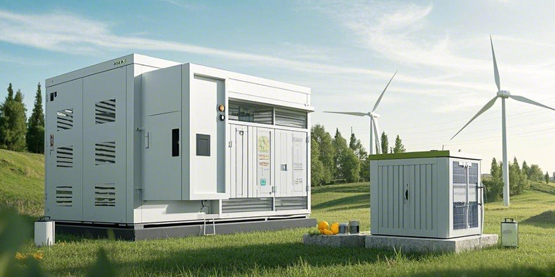
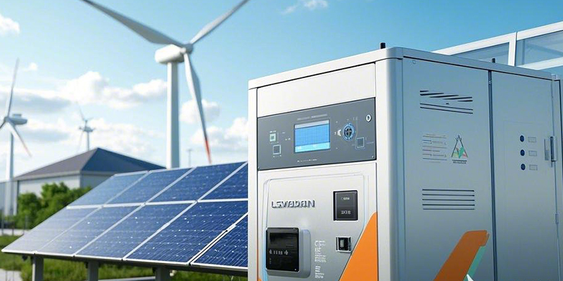
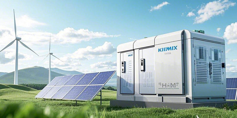
In the global push toward energy transformation, clean energy sources like solar and wind power are playing a pivotal role. According to data from the International Energy Agency (IEA), renewable energy now accounts for over 30% of global electricity supply, with expectations of rapid growth over the next decade. However, the widespread adoption of clean energy faces a core challenge—intermittency. Solar power depends on sunlight availability, while wind power is subject to fluctuating wind speeds, making stable energy supply a significant hurdle.
To address this issue, efficient clean energy storage technologies are essential. Advanced battery technologies allow us not only to store surplus clean energy but also to ensure the stability of energy systems during peak demand or low production periods, thereby advancing sustainability goals. So, how can businesses choose the best battery solutions for solar and wind power? This article will provide detailed answers to this question, helping you make informed decisions in the field of energy storage.
1. Battery Technology Overview: Mainstream Options for Clean Energy Storage
Before diving into storage solutions for solar and wind power, it’s important to understand the mainstream battery technologies currently available. Different battery types offer unique advantages in terms of energy density, lifespan, cost, and application scenarios. Below is an overview of several common battery technologies and their key features:
Lithium-Ion BatteriesLithium-ion batteries are renowned for their high energy density and long cycle life, making them an excellent choice for small to medium-scale solar systems. They excel in charge-discharge efficiency, making them ideal for applications requiring frequent cycling, and are a popular option in the clean energy storage sector.
Lead-Acid Batteries Lead-acid batteries are a traditional technology with a low upfront cost, suitable for short-term storage needs. However, they have lower energy density, shorter cycle life, and lower efficiency compared to lithium-ion batteries, making them more appropriate for budget-constrained small-scale projects.
Flow Batteries Flow batteries are known for their long-duration storage capabilities and scalability, making them ideal for large-scale wind power systems. While their initial cost is higher, they offer low maintenance costs and are well-suited for scenarios requiring extended discharge periods.
Sodium-Ion Batteries As an emerging technology, sodium-ion batteries are gaining attention for their low cost and environmental benefits. Although their energy density is lower than that of lithium-ion batteries, their potential lies in resource availability and sustainability, positioning them as a promising future option for clean energy storage.
Solid-State Batteries Solid-state batteries represent the future of battery technology, offering high safety and long lifespan. However, due to their current technological immaturity, they remain limited in commercial applications.
2. Best Battery Solutions for Solar Power: Technology and Case Studies
For solar power users, selecting the right battery solution is key to achieving efficient storage. Based on market validation and real-world applications, lithium-ion batteries are considered the top choice for solar energy storage. Below is an analysis of their core advantages and related insights:
Technical Parameter Comparison
Lithium-ion batteries stand out in several critical parameters:
Energy Density: Compared to lead-acid batteries, lithium-ion batteries offer several times higher energy density, allowing more energy to be stored in a smaller space.
Charge-Discharge Efficiency: Their efficiency typically exceeds 90%, minimizing energy loss to the greatest extent possible.
Cycle Life: High-quality lithium-ion batteries can achieve over 5,000 cycles, significantly extending their service life.
Real-World Case Study
Consider the example of a commercial business park. This park installed a rooftop solar power system paired with a lithium-ion battery storage solution. Using an intelligent energy management system, the park stores excess solar energy during the day and uses the stored energy at night or on cloudy days. This approach not only reduces electricity costs but also decreases reliance on the traditional grid, achieving efficient energy utilization.
Design Recommendations for Solar Storage Systems
When designing a solar energy storage system, businesses should pay attention to the following:
Inverter Pairing: Choose a high-efficiency inverter to minimize energy loss during conversion.
Battery Management System (BMS): A BMS can monitor battery status in real time, optimize charge-discharge strategies, and enhance both battery lifespan and safety.
3. Best Battery Solutions for Wind Power: Technology and Case Studies
For wind power users, the inherent variability of wind speeds means storage systems must offer long-duration storage and high capacity scalability. Based on market validation, flow batteries are considered the best choice for wind energy storage. Below is an analysis of their core advantages and related insights:
Technical Parameter Comparison
Flow batteries excel in several key parameters:
Capacity Scalability: The capacity of flow batteries can be expanded by adding more electrolyte tanks, making them ideal for large-scale wind farms.
Maintenance Costs: Compared to other battery technologies, flow batteries have lower maintenance costs and a long service life.
Environmental Adaptability: Flow batteries can operate reliably in extreme conditions, making them suitable for the complex climates often encountered in wind power projects.
Real-World Case Study
Take the example of a coastal wind farm. This wind farm deployed a flow battery storage system to store excess energy generated during nighttime or high-wind periods, supplying power to the grid during low-wind periods. This approach not only increases energy utilization efficiency but also enables peak-valley load balancing, significantly reducing operating costs.
Design Recommendations for Wind Storage Systems
When designing a wind energy storage system, businesses should focus on the following:
Grid Integration: Leverage smart grid technology to optimize the input and output of stored energy, ensuring seamless integration with the grid.
Peak-Valley Load Balancing: Use the long-duration storage capabilities of flow batteries to store energy during low-price periods and release it during high-price periods, thereby reducing electricity costs.
By implementing a scientifically designed system, businesses can fully harness the potential of wind energy battery solutions.
4. How to Choose the Right Battery Solution: Key Decision Factors
When selecting the best battery solution, businesses must consider multiple factors to maximize return on investment (ROI). Below are several key decision factors:
Cost Considerations
Businesses need to balance upfront investment costs against long-term operating costs. For example, lithium-ion batteries have a higher initial cost, but their high efficiency and long lifespan can significantly reduce long-term operating costs. In contrast, lead-acid batteries have a lower upfront cost but require more frequent maintenance and replacement.
Scale Requirements
Different project scales have varying battery solution needs. Small commercial projects may be better suited for lithium-ion batteries, while large industrial projects, such as wind farms, are better served by flow batteries.
Environmental Factors
The environmental footprint and recyclability of batteries are important considerations in solution selection. Sodium-ion and flow batteries perform well in terms of environmental impact, while recycling technologies for lithium-ion batteries are also advancing.
Policy Support
In the United States, clean energy storage projects can benefit from various policy incentives, such as the Investment Tax Credit (ITC) and state-level subsidies. Businesses should take full advantage of these policies to reduce costs when selecting a solution.
Technical Support
Choosing a reliable supplier is critical to the successful implementation of a storage project. Businesses should evaluate a supplier’s after-sales service capabilities, technical support levels, and ability to provide customized solutions.
As clean energy adoption continues to grow, efficient storage technologies are becoming critical for businesses aiming to achieve energy transformation and sustainability goals. Through the analysis in this article, we can see that lithium-ion batteries are the ideal choice for solar energy storage, while flow batteries are the best solution for wind energy storage. When selecting a battery solution, businesses should comprehensively consider factors such as cost, scale, environmental impact, and policy support to ensure maximum energy efficiency and economic benefits.
Choosing the right clean energy storage solution not only enhances a business’s energy utilization efficiency but also contributes positively to sustainability efforts. As a leading provider of battery solutions, HIMAX Electronics is committed to offering customized battery solutions to help your clean energy projects succeed. Contact us today to learn more about how we can support your journey toward efficient energy management!
https://himaxelectronics.com/wp-content/uploads/2025/03/wind_energy_storage.webp400800administrator2/wp-content/uploads/2019/05/Himax-home-page-design-logo-z.pngadministrator22025-03-12 14:21:552025-03-12 14:21:55How to Efficiently Store Clean Energy: Exploring the Best Battery Solutions for Solar and Wind Power
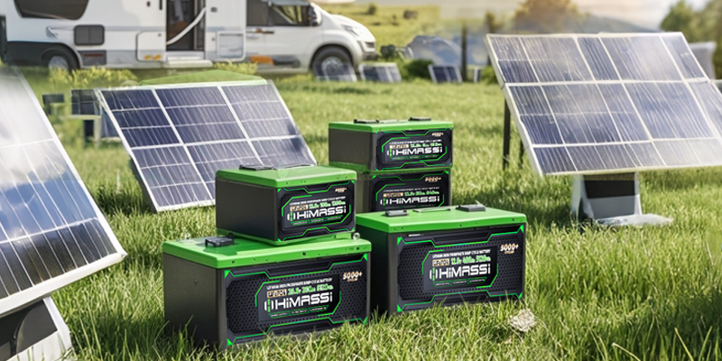
Whether you’re enjoying the freedom of RV camping or navigating the open waters, a reliable battery is the heart of your RV or marine setup. In the RV and marine industries, batteries not only need to deliver consistent power but also meet strict requirements for space, weight, and safety. Among the many options, LiFePO4 battery(lithium iron phosphate) and lead-acid batteries are the two most common choices for RV and marine batteries (RV and marine battery). But how do you decide which one is right for your needs? This article dives into the technical basics, performance comparisons (lithium iron phosphate vs lead-acid), real-world applications, and practical tips to help you make an informed decision and find the best battery solution for your RV camping or marine adventures.
Understanding the Basics of Lithium Iron Phosphate and Lead-Acid Batteries
To choose the right RV and marine battery (RV and marine battery), it’s essential to understand the fundamental principles and technical features of LiFePO4 batteryand lead-acid batteries.
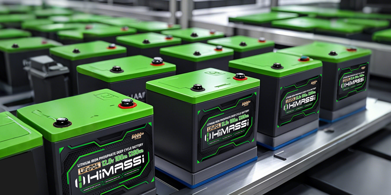
LiFePO4 battery(Lithium Iron Phosphate): This type of battery uses lithium iron phosphate as its cathode material, generating electricity through the movement of lithium ions between the cathode and anode. Its working principle relies on a stable voltage platform (typically 3.2V per cell), offering high energy density and a long cycle life.
Lead-Acid Battery: Lead-acid batteries use lead and sulfuric acid as their primary components, producing electricity through an electrochemical reaction between lead and acid. While this technology is mature and cost-effective, it has lower energy density and is significantly heavier.
The key differences between the two lie in energy density, weight, lifespan, and safety. For instance, LiFePO4 battery offers much higher energy density and lighter weight, making it ideal for space-constrained RVs and boats, while lead-acid batteries, though cheaper, have a shorter lifespan and require more maintenance. Understanding these basics will help you make sense of the comparisons that follow.
Performance Comparison: Lithium Iron Phosphate vs. Lead-Acid Across Five Key Metrics
When selecting an RV or marine battery, performance is the top priority. Below, we compare LiFePO4 batteryand lead-acid batteries (lithium iron phosphate vs lead-acid) across five critical metrics to help you fully understand their strengths and weaknesses.
Energy Density and Weight: LiFePO4 batteryboasts significantly higher energy density than lead-acid batteries, weighing only about one-third as much. This means that for the same capacity, LiFePO4 battery takes up less space and is much lighter, making it ideal for RVs and boats with limited space. In contrast, lead-acid batteries are heavy, potentially increasing the load on your vehicle or vessel, which can impact fuel efficiency or range.
Cycle Life: LiFePO4 battery offers a cycle life of 2,000 to 5,000 cycles, far surpassing lead-acid batteries’ 200 to 500 cycles. This means that over the long term, LiFePO4 battery requires fewer replacements, making it more cost-effective in the long run.
Charging Efficiency and Speed: LiFePO4 batterysupports fast charging with a discharge efficiency of over 90%, while lead-acid batteries charge more slowly and have a lower efficiency (around 70-80%), performing poorly in scenarios requiring frequent charging and discharging.
Environmental Adaptability: LiFePO4 battery outperforms lead-acid batteries in extreme temperatures, maintaining stable power output in both hot and cold conditions, which is especially important for marine applications in harsh environments. Lead-acid batteries, on the other hand, suffer significant capacity loss in cold temperatures, requiring additional insulation measures.
Safety: LiFePO4 batteryoffers superior thermal stability, reducing the risk of fire or explosion, making it safer than lead-acid batteries. Lead-acid batteries carry risks of acid leaks and explosions, particularly in the high-humidity environments of marine applications, requiring extra safety precautions.
To make the comparison clearer, the table below summarizes the performance of LiFePO4 battery and lead-acid batteries across these five metrics:
Metric
LiFePO4 battery
Lead-Acid Battery
Energy Density
High (Lightweight)
Low (Heavy)
Cycle Life
2,000–5,000 cycles
200–500 cycles
Charging Efficiency & Speed
High (Fast Charging)
Low (Slow Charging)
Environmental Adaptability
Excellent (Handles Extreme Temperatures)
Poor (Cold Weather Decline)
Safety
High (Good Thermal Stability)
Moderate (Acid Leak Risk)
Real-World Performance in RV and Marine Applications
The performance differences between LiFePO4 battery and lead-acid batteries become even more apparent in real-world RV and marine applications. Below, we explore specific scenarios to highlight their practical performance (best RV battery 2025, marine battery comparison):
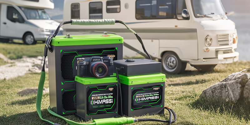
RV Scenarios: During RV camping, batteries need to support extended off-grid use, powering appliances like refrigerators, lights, and air conditioners. LiFePO4 battery, with its high energy density and long cycle life, excels at providing extended runtime. For example, HIMAX Electronics supplied a 200Ah LiFePO4 battery pack to a U.S.-based RV manufacturer, enabling their RV to run off-grid for over three days on a single charge. In contrast, lead-acid batteries in similar scenarios typically support only about a day of power needs and are much heavier, impacting the RV’s overall design.
Marine Scenarios: In marine navigation systems, batteries must deliver reliable power in high-humidity environments. LiFePO4 battery, with its excellent corrosion resistance and high safety, is the ideal choice. HIMAX Electronics designed a 100Ah LiFePO4 batterypack for a marine manufacturer to power navigation and communication equipment, maintaining stable performance even in wet marine conditions. Lead-acid batteries, while viable for low-power applications, require frequent maintenance in long-term use and are prone to acid leaks in high-humidity environments.
Cost and Return on Investment Analysis
Cost is a critical factor when choosing an RV or marine battery. Below, we analyze LiFePO4 battery and lead-acid batteries in terms of initial cost, maintenance cost, and long-term return on investment (lithium battery for RV camping).
Initial Cost: LiFePO4 batteryhas a higher upfront cost, typically 2-3 times that of lead-acid batteries. For example, a 100Ah LiFePO4 batterymight cost over $500, while a comparable lead-acid battery might cost just $200. However, initial cost is not the only factor to consider.
Maintenance Cost: Lead-acid batteries require regular maintenance, such as checking electrolyte levels and adding distilled water, while LiFePO4 battery is virtually maintenance-free, reducing long-term maintenance costs.
Replacement Frequency: Due to its significantly longer cycle life, LiFePO4 batteryrequires fewer replacements. For instance, a LiFePO4 batterymight last 8-10 years, while a lead-acid battery might need replacement every 2-3 years, lowering the total cost of ownership (TCO) over time.
Return on Investment: The chart below compares the total cost of both battery types over five years (assuming a 100Ah capacity and daily RV power consumption of 50Ah):
Battery Type
Initial Cost
Maintenance Cost (5 Years)
Replacement Frequency (5 Years)
Total Cost (5 Years)
LiFePO4 battery
$500
$0
0
$500
Lead-Acid Battery
$200
$100
2
$600
Over the long term, LiFePO4 battery offers a better return on investment, especially for RV and marine users with long-term needs.
How to Choose the Right RV and Marine Battery
Choosing the right RV or marine battery (how to choose RV and marine battery) involves evaluating multiple factors. Below are the key steps to guide your decision (RV battery comparison):
Needs Assessment: Analyze your RV or marine power needs, including daily consumption (e.g., refrigerator, lights, navigation equipment), equipment type (AC or DC), and space/weight constraints. For example, if your RV requires extended off-grid camping, LiFePO4 battery might be the better choice.
Usage Scenarios: Consider your primary use case. If you only go on short camping trips or boating outings and have a limited budget, lead-acid batteries may be more cost-effective. However, if you need extended off-grid use or operate in extreme environments, LiFePO4 battery is the superior option.
Safety and Regulations: RVs and boats have strict safety requirements, especially in the U.S. market, where batteries must comply with UL certification (battery safety standards) or ABYC marine standards (waterproofing, corrosion resistance). LiFePO4 battery offers superior safety, making it particularly suitable for marine environments.
Partnering with a Supplier: Working with a professional battery supplier is key to success. HIMAX Electronics not only provides technical consultation but also designs and tests custom battery solutions tailored to your needs, ensuring the best balance of performance, safety, and cost.
Through a comprehensive comparison of lithium iron phosphate and lead-acid batteries (lithium iron phosphate vs lead-acid), we’ve found that LiFePO4 battery excels in performance, lifespan, and safety, making it the ideal choice for long-term RV and marine applications, especially in scenarios requiring high energy density, extended runtime, and extreme environmental adaptability. Lead-acid batteries, on the other hand, remain a cost-effective option for budget-conscious users in short-term scenarios. HIMAX Electronics is dedicated to providing professional RV and marine battery (RV and marine battery) solutions, helping your equipment achieve peak performance. Visit the HIMAX Electronics website today, contact our expert team, and explore the best battery solution for your RV camping or marine navigation needs—start your battery upgrade journey now!
https://himaxelectronics.com/wp-content/uploads/2025/03/LiFePO4_vs._lead-acid_batteries.webp400800administrator2/wp-content/uploads/2019/05/Himax-home-page-design-logo-z.pngadministrator22025-03-11 06:17:142025-03-11 06:17:14The Ultimate Guide to RV and Marine Batteries: Lithium Iron Phosphate vs. Lead-Acid – Which Is Your Best Choice?