Introduction
In the evolving landscape of modern energy solutions, energy storage systems (ESS) have emerged as a critical component in enhancing efficiency and integrating renewable resources effectively. These systems are particularly pivotal in managing the variability of solar power, enabling a steady and reliable energy supply despite the inherent intermittency of solar resources. Proper configuration of photovoltaic (PV) panels is essential to meet specific energy storage capacities and daily load demands. This guide explores the nuanced considerations necessary for determining the optimal PV panel setup tailored to both the storage capacity and the energy consumption patterns of various applications.
Fundamentals of Energy Storage Systems
Energy storage systems are instrumental in bridging the gap between energy production and consumption. By storing excess energy during periods of low demand and high production, such as sunny midday hours, and releasing it during high demand or low production periods, ESS helps stabilize the grid and ensure a consistent energy supply. The interplay between photovoltaic panels and energy storage systems is crucial, as the efficiency of energy conversion and storage directly impacts the overall system performance.
Energy storage not only supports grid stability but also enhances the utilization of renewable energy sources by mitigating issues related to their unpredictability. For instance, during cloudy or rainy days when solar output is reduced, stored energy can compensate for the shortfall, maintaining energy supply without the need for conventional grid reliance. Furthermore, advanced energy storage systems can provide critical services such as peak shaving, load leveling, and emergency backup, making them indispensable in modern energy infrastructures.
Understanding how photovoltaic panels contribute to and interact with energy storage systems involves a grasp of the basic electrical principles, including voltage, current, and power generation dynamics under varying environmental conditions. The effectiveness of an ESS often hinges on the capability of PV panels to convert sunlight into electrical energy efficiently and reliably feed that energy into storage units configured to handle specific load requirements.
Battery Capacity and Photovoltaic Panel Configuration
Choosing the right configuration for photovoltaic panels is critically dependent on the capacity of the batteries that store the generated electricity. This relationship is vital because the battery’s capacity dictates how much energy needs to be stored, which in turn influences the size and output of the PV panels needed.
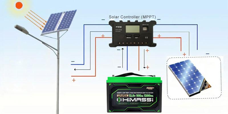
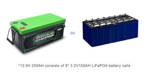
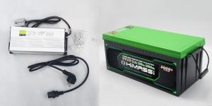
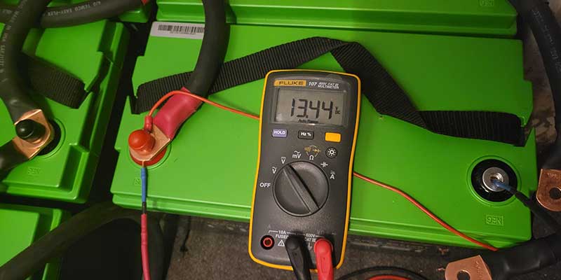
For example, consider a typical setup where the battery bank consists of a 12.8V system with a capacity of 200AH. This setup is tasked with managing a daily load of 2 kWh. To meet this demand efficiently, the configuration of the photovoltaic panels must align precisely with both the energy consumption needs and the storage capacity. If the goal is to ensure the battery is fully charged over the course of a single day, the calculation of the necessary photovoltaic output becomes crucial.
- Example Calculation: With an 800W photovoltaic panel system receiving an average of 4.5 effective hours of sunlight per day, the total energy produced would be 800W times 4.5 hours, equating to 3600W. Factoring in a conservative estimate of system efficiency at 70%, the usable energy produced would amount to 2520W. Given the battery capacity is 2560WH, an 800W photovoltaic panel would be nearly perfect to meet the daily charge requirement, demonstrating a well-matched system configuration.
This calculation shows the importance of aligning photovoltaic panel output with battery storage capacity to ensure energy is neither wasted nor insufficient. It highlights how critical the precise calculation of panel output, sunlight availability, and system efficiency is to the successful implementation of a photovoltaic system tied to energy storage.
Calculating Photovoltaic Panel Configuration
Determining the ideal photovoltaic panel configuration requires a detailed understanding of daily energy needs, anticipated energy production, and system efficiency considerations. Here’s a step-by-step approach to calculate the necessary photovoltaic output based on different requirements:
- Determine Daily Energy Requirements: Start by calculating the total energy consumption of the system per day, factoring in all appliances and devices that will draw power from the storage system.
- Assess Effective Sunshine Hours: Evaluate the average number of effective sunlight hours available in your location. This varies widely based on geographical location, season, and local weather patterns.
- Account for System Efficiency: Include considerations for losses due to inverter efficiency, potential energy loss from heat dissipation, and inefficiencies in wiring and connections. A common efficiency factor to use in these calculations is around 70-80%, but this may vary based on specific system components and configurations.
- Plan for Backup Energy Needs: If the system needs to provide energy during multiple consecutive days without sunlight, the configuration must account for additional storage capacity and potentially increased photovoltaic output to charge the battery bank fully during periods of available sunlight.
For instance, if the requirement extends to fully charging the battery over two days with limited sunshine, adjusting the photovoltaic panel capacity becomes necessary. Under the same efficiency and sunlight conditions, a 400W panel might suffice, providing a slower charge rate but meeting the extended duration requirement.
Choosing the Right Photovoltaic Panels
Selecting the appropriate photovoltaic (PV) panels is critical for optimizing the performance and longevity of energy storage systems. When choosing PV panels, several factors must be considered to ensure that they meet the specific needs of the system and provide the best possible return on investment.
- Efficiency: One of the most important characteristics of a PV panel is its efficiency, which refers to how well it converts sunlight into electricity. Higher efficiency panels generate more power per square foot, which is beneficial in scenarios where space is limited. While these panels may carry a higher upfront cost, they can provide greater long-term savings by maximizing energy production, especially in areas with high sunlight exposure.
- Durability: The environmental conditions where the panels will be installed play a significant role in selecting the right type. Panels must be durable enough to withstand local weather conditions such as heavy rains, high winds, and potential hail. Additionally, the quality of materials and the construction of the panels affect their ability to endure long periods of exposure to UV rays and other environmental stressors.
- Cost: The cost of PV panels can vary significantly based on factors such as efficiency, durability, and brand reputation. It’s essential to balance the initial investment against expected energy production and potential savings. In many cases, spending more upfront on higher quality, more efficient panels can lead to higher savings in energy costs over the life of the system.
- Warranty and Manufacturer Support: The warranty period offered by the manufacturer can provide insights into the expected lifespan and reliability of the panels. Longer warranty periods and comprehensive support reflect confidence in the product and can help safeguard your investment.
Case Studies and Real-world Applications
Analyzing real-world applications of photovoltaic panel configurations in energy storage systems provides valuable insights into their practical effectiveness and challenges. Here are some case studies that illustrate the impact of well-chosen PV configurations:
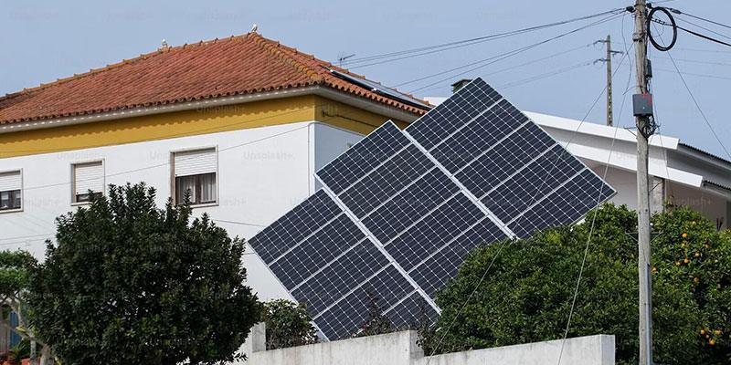
- Residential Installation in a Temperate Climate: In this case, a homeowner in a region with moderate sunlight installed a system consisting of high-efficiency panels. Despite the higher initial cost, the panels’ ability to produce more energy per square foot allowed the homeowner to meet 100% of their energy needs year-round, significantly reducing their reliance on grid electricity.
- Commercial System in a High Sunlight Area: A commercial entity in a desert area opted for durable, moderately efficient panels that could withstand intense sun and heat without degrading. The system was designed to handle high daytime loads and provide substantial energy back to the grid, demonstrating the importance of durability and efficiency in harsh climates.
- Rural Off-grid System: In a remote location with limited access to reliable grid power, an off-grid system with robust PV panels and a large battery storage capacity was implemented. This setup ensured that the community had continuous power, even in variable weather conditions, highlighting the system’s resilience and the critical role of comprehensive energy planning.
Conclusion
The configuration of photovoltaic panels in an energy storage system is not just a technical decision—it’s a strategic one that impacts the efficiency, reliability, and financial viability of the system. Accurate configuration ensures that the system can meet daily energy demands, adapt to environmental conditions, and provide sustainable energy solutions over the long term. By carefully matching photovoltaic panels to the system’s battery capacity and load requirements, users can maximize their energy yield, reduce dependency on traditional power grids, and contribute to a more sustainable future. This process, though complex, offers significant rewards in terms of energy independence and environmental impact.
About Himax Electronics
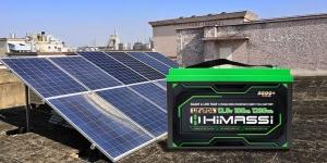
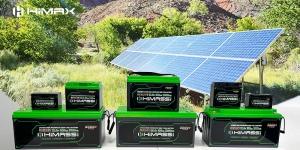
Himax Electronics stands at the forefront of the solar energy and battery storage industries, providing innovative SOLAR BATTERY solutions that push the boundaries of what’s possible in renewable energy technology. With a focus on high-efficiency photovoltaic solutions and robust energy storage systems, Himax is dedicated to helping clients harness the power of the sun to meet their diverse energy needs.
- Expertise and Innovation: At Himax, innovation is at the core of everything we do. Our team of experts continually develops new technologies and solutions that improve the efficiency and reliability of photovoltaic systems. From advanced MPPT controllers to high-capacity batteries, our products are designed to offer superior performance in a wide range of applications.
- Commitment to Sustainability: Himax is deeply committed to promoting sustainable energy practices. By focusing on renewable sources and advanced storage solutions, we help reduce carbon footprints and promote energy independence for our clients. Our goal is to make renewable energy accessible and effective for everyone, from individual homeowners to large commercial enterprises.
- Customer-Centric Solutions: Understanding that each client has unique energy needs, Himax offers customized solutions tailored to the specific requirements of each project. Our comprehensive support system ensures that clients receive the guidance and resources they need to successfully implement and maintain their energy systems. From initial consultation to post-installation support, Himax is with you every step of the way.
- Global Impact: With a presence in multiple countries and a diverse portfolio of successful projects, Himax Electronics is a global leader in the solar energy sector. Our international experience and broad expertise enable us to handle projects of any scale and complexity, driving the global transition to renewable energy.
In conclusion, choosing the right photovoltaic panel configuration for your energy storage system is crucial for optimizing performance and achieving long-term sustainability. Himax Electronics is your trusted partner in this journey, offering the expertise, products, and support needed to transform the way you harness solar energy.