By Dawn • Battery Engineer, Safety & Compliance • Himax Electronics • July 2026
Topics: Medical Battery Pack / Li-ion Safety / BMS / IEC 62133 / Custom Pack Development
Designing a medical device battery pack 25.2V requires more than just picking cells and wiring them together. When a medical device team reaches out about a custom battery, the first question they ask is usually about voltage or capacity. The second is usually about size. By the third conversation, the question that actually matters surfaces: “What does certification require, and how does that impact our timeline?”
However, that shift in concern is entirely predictable, and it’s the one I prepare for in every medical battery development engagement. Certification is not a step that happens after the battery is designed. It’s a constraint that shapes the design from the first component selection. Get it wrong early and you’re doing a redesign at the worst possible time — when the device team is already pressure-testing their regulatory submission schedule.
This post is about what it actually takes to design a 25.2V 2000mAh lithium-ion battery pack for a portable medical device correctly. I’ll cover the configuration rationale, the BMS requirements that are specific to medical applications, the certification landscape, the pass-through charging question that comes up in almost every portable medical device project, and the physical design constraints that make this category different from industrial or consumer battery work.
I’m writing this for engineers and product managers at medical device companies who are in the early-to-mid stage of a battery development conversation and want to understand what they’re getting into before committing to a supplier.
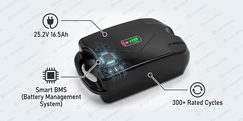
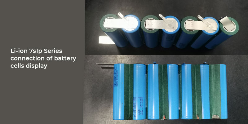
Why 25.2V? The Voltage Architecture of a 7S1P Li-ion Pack
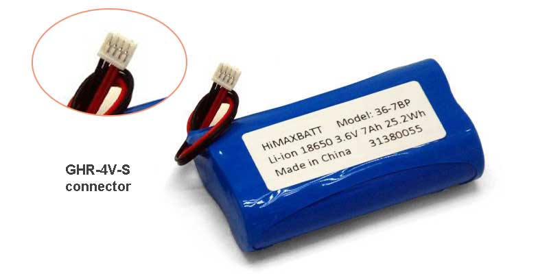
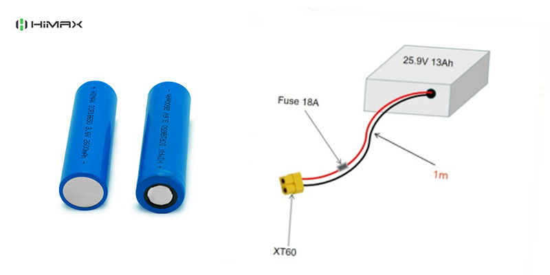
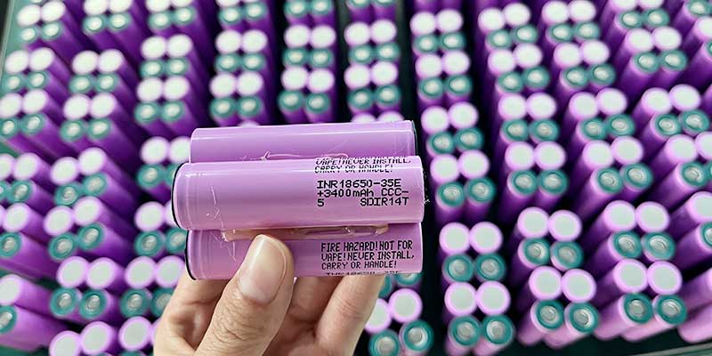
A 25.2V nominal voltage in a lithium-ion pack means seven cells in series (7S). Each standard lithium-ion 18650 cell, for instance, has a nominal voltage of 3.6V, and 7 × 3.6V = 25.2V. The full-charge voltage is 4.2V per cell, giving a pack charge voltage of 29.4V. We typically set the discharge cutoff at 3.0V per cell, giving a pack cutoff of 21.0V. This is the operating window your device’s electronics need to accommodate.
The 1P in 7S1P means a single cell per parallel group — one cell at each of the seven series positions. This gives a pack capacity equal to the capacity of a single cell: 2000mAh (using 18650 cells with 2000mAh rated capacity). The total energy is 50.4Wh (25.2V × 2.0Ah), which falls within the 20–40Wh range that’s common for portable medical devices in the 24V system class.
Why Not a Higher-Capacity Cell?
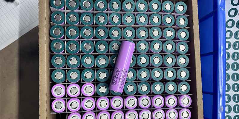
A natural follow-up question is why use a 2000mAh cell rather than a 3000mAh or 3400mAh cell, which are also available in 18650 format. The answer for medical applications comes down to two factors: validated performance data and certification traceability.
Higher-capacity 18650 cells are optimized for energy density, which sometimes comes at the cost of discharge rate capability and cycle life consistency. A 2000mAh cell in a medical application where the continuous discharge current is 2.0A (1C rate) is operating at a moderate, well-characterized load. The same cell at 2.0A discharge with a 3400mAh cell would be at 0.59C — which sounds better, but the cell selection should be driven by the actual load profile and certification history, not simply by maximizing capacity. In medical development, a well-documented cell with a clean safety and certification record is worth more than an extra 400mAh.
Pack Dimensions and Physical Constraints
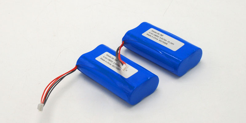
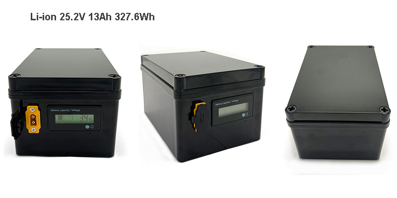
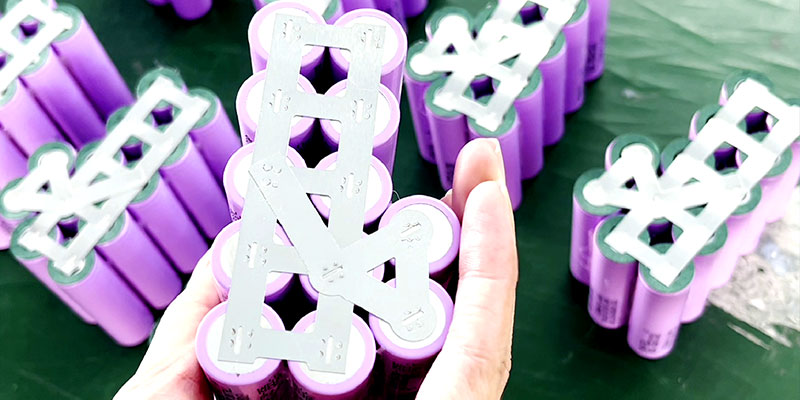
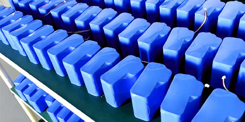
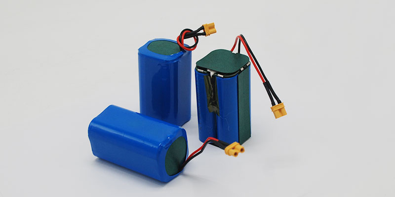
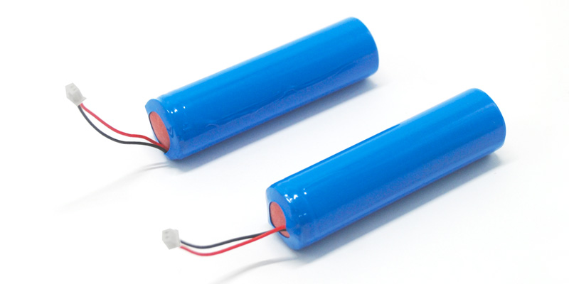
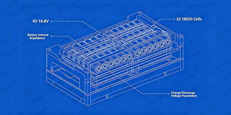
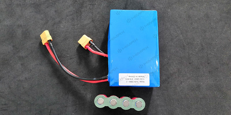
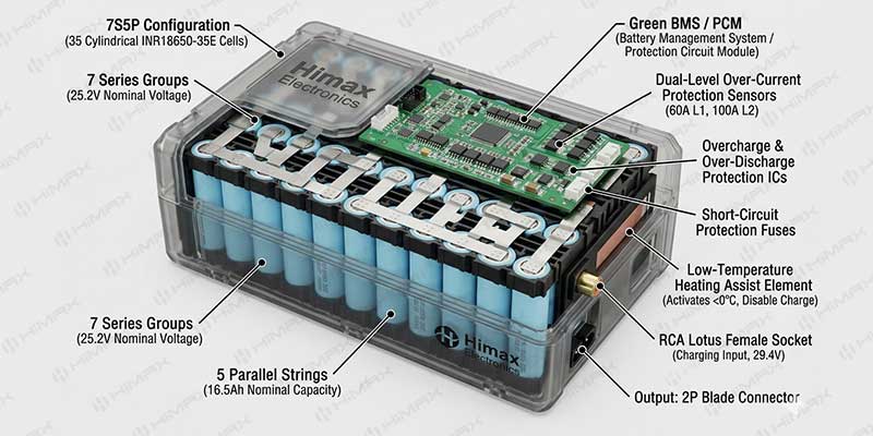
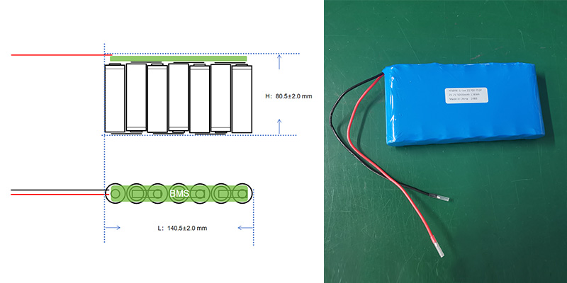
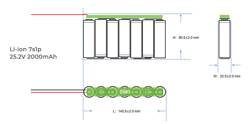
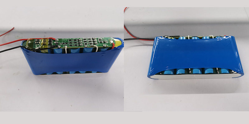
The preliminary configuration for a 7S1P 18650 pack in this class produces a pack with approximate dimensions of 140.5 × 22.5 × 80.5mm (±2.0mm) and a weight of approximately 350g. The layout positions the seven cells side by side in a single row, with the BMS board running along the base of the cell array.
Figure 1: 7S1P 18650 pack layout — L: 140.5±2.0mm × W: 22.5±2.0mm × H: 80.5±2.0mm. BMS board positioned along the cell base.
However, a few things to note about these dimensions for device integration:
- 5mm width is narrow enough to fit in a grip area or a handle cavity on most briefcase-format portable instruments.
- 5mm length is close to the length of a standard AA battery holder × 7 — which gives an intuitive sense of the longitudinal footprint inside a device housing.
- 5mm height is the dimension most often negotiated in custom pack development: if device housing height is constrained, the cell orientation or BMS placement can be adjusted to reduce this dimension, with a corresponding increase in length or width.
- 350g weight is meaningful in a portable device context. If the total device target weight is under 2kg, the battery represents roughly 17–18% of the budget — which is typical and reasonable for this energy class.
Consequently, these dimensions are a preliminary starting point, not a constraint. Custom battery development for medical devices almost always involves iterating the physical design alongside the device housing design. The cell chemistry, voltage, and capacity are fixed by the 7S1P 18650 configuration; the physical arrangement of those cells and the BMS can be adapted to whatever 3D envelope the device team specifies.
The BMS: What “Integrated Smart BMS” Actually Means in a Medical Context
Every battery supplier will tell you their pack includes a BMS. In medical device applications, what the BMS does — and how it communicates with the device — matters considerably more than in consumer or industrial applications. Let me break down what a well-specified BMS looks like for this application.
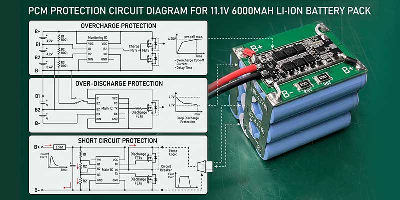
Protection Functions
These are the baseline safety functions that any BMS in a medical battery must include:
- Overcharge protection: disconnects the charge path if any cell reaches 4.25–4.28V, preventing lithium plating and thermal events during charging
- Over-discharge protection: disconnects the discharge path if any cell drops below 2.5–3.0V, preventing irreversible capacity loss and cell damage
- Overcurrent protection: limits discharge current to the rated maximum (2.0A continuous, 6.0A peak ≤1 second for this configuration) and disconnects on fault
- Short-circuit protection: hardware-level cutoff in microseconds on external short circuit detection
- Temperature protection: thermistor monitoring with charge inhibit below 0°C and above 45°C, discharge inhibit at temperature extremes. Critical in medical applications where the battery may be near a patient or in a heated enclosure
Communication Interface: SMBus, UART, or I2C
Standard consumer battery BMS designs have no communication interface — they protect and that’s all. Medical devices almost always need more. The device firmware needs to know:
- Remaining capacity (state of charge as a percentage or mAh remaining)
- State of health (capacity relative to original rated capacity)
- Current pack voltage and cell-level voltages (for imbalance detection)
- Temperature
- Fault status and error codes
- Cycle count
These data are surfaced through a communication bus — SMBus (the most common in medical devices), UART, or I2C depending on the device controller architecture. SMBus is based on the Smart Battery Specification (SBS), which defines a standard register set that many medical device firmware teams already have drivers for. If your device uses an SMBus fuel gauge, specifying SMBus compatibility at the battery level is the path of least integration friction.
| Design note from the field:
One of the most common integration problems I see in medical battery projects is a mismatch between the BMS communication protocol and what the device firmware team assumed. “Smart BMS” on a spec sheet could mean SMBus, UART, I2C, or a proprietary protocol. Specify the protocol and register map you need before the prototype is built — retrofitting the communication interface adds weeks to the development schedule. |
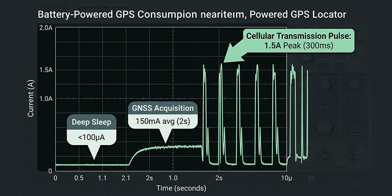
Pass-Through Charging: Operating While Connected to External Power
This is the requirement that comes up in nearly every portable medical device project and generates the most confusion: the device must be able to operate while connected to external power, and the battery must support this without degradation.
In battery engineering, this is called pass-through charging or power path management. The behavior is: when external power (the charger) is connected, the device draws power from the charger — not the battery. The battery charges in the background. When external power is removed, the device transitions seamlessly to battery power.
Implementing this correctly requires either:
- A power path management IC on the device board (preferred for precise control) that handles the charger-to-battery switchover — not a battery-level feature, but a device-level design
- A BMS with integrated pass-through support (less common, but available) where the BMS manages both the charge and load paths simultaneously with minimal voltage transient on switchover
Specifically, the key concern in medical applications is what happens to device operation during the switchover. A brief voltage dip during the transition from charger to battery can cause microcontroller resets or sensor glitches in sensitive medical electronics. Switchover time and voltage transient specs should be defined as part of the battery-device interface requirements, not assumed.
Certification: The Standards That Matter and What They Actually Test
Unsurprisingly, this is where I spend the most time in early medical battery development conversations, because it’s the area where misconceptions are most costly. Let me go through the relevant standards and what each one actually requires.
UN38.3 — Transport Safety
UN38.3 is a transport certification, not a product safety certification. It certifies that lithium-ion cells and batteries are safe to transport by air, sea, and road. The test protocol includes: altitude simulation, thermal cycling, vibration, shock, external short circuit, impact/crush, overcharge, and forced discharge. The battery pack and its cells must pass all eight tests for most configurations.
UN38.3 is required by law for any shipment of lithium-ion batteries by air or sea. It’s not optional if you’re importing or exporting your device. But it’s not a medical device safety standard — it doesn’t evaluate the battery’s performance in service or its compatibility with medical device requirements. Think of it as the floor, not the ceiling.
IEC 62133 — Battery Safety for Portable Applications
IEC 62133 is the product safety standard for rechargeable battery cells and packs used in portable applications. It covers electrical and mechanical safety tests including continuous charge, abnormal charge, forced discharge, external short circuit, free fall, mechanical shock, vibration, and thermal abuse. The standard has two parts: Part 1 for Ni-MH and Part 2 for lithium systems (which is what applies here).
IEC 62133-2 certification is commonly required by retailers and importers for lithium-ion products sold in Europe, North America, and Asia-Pacific. For medical devices, it’s often a prerequisite for the device-level regulatory submission because it provides independent third-party evidence that the battery has been tested to a recognized safety standard.
One important clarification: IEC 62133 certifies the battery as a component, not the device as a system. If your device regulatory pathway requires a system-level battery safety evaluation (which some medical device categories do), IEC 62133 certification of the battery component supports but does not replace that evaluation.
IEC 62619 — For Industrial and Higher-Power Applications
IEC 62619 is relevant if your device falls into a higher-power or stationary/semi-stationary category. For a 25.2V 2000mAh portable device with a maximum 2A continuous discharge, IEC 62133-2 is typically the applicable standard. IEC 62619 covers secondary lithium cells in industrial applications and becomes relevant when the pack power is above the IEC 62133 scope, or when the device is classified as industrial rather than consumer/portable.
CE Marking for Medical Devices (EU MDR 2017/745)
If your device is sold in the EU, the battery pack needs to be addressed in your device’s technical documentation under the EU Medical Device Regulation (MDR 2017/745). The battery is a critical electrical subsystem, and the MDR requires demonstration that it meets the General Safety and Performance Requirements (GSPR) of Annex I.
In practice, this means the battery supplier needs to provide: a declaration of conformity, the applicable test reports (UN38.3, IEC 62133), traceability documentation for the cells used, and a MSDS/SDS for the battery. The device manufacturer incorporates this documentation into their technical file.
| Certification checklist for a 25.2V 2000mAh medical battery pack (EU market):
• UN38.3 — required for transport (cell-level and pack-level) • IEC 62133-2 — product safety standard for lithium-ion portable batteries • CE Declaration of Conformity — for devices placed on the EU market • MSDS / SDS — material safety data sheet for the battery pack • Traceability documentation — cell manufacturer, batch, test reports • Optional: IEC 62619 if device classification requires it • Optional: UL 2054 or UL 1642 for US market (UL listing, not always mandatory for Class II medical devices but increasingly expected by hospital buyers) |
The Development Process: From Inquiry to Certified Sample
In practice, medical device teams often underestimate how long the battery development and certification path takes. Here is an honest timeline overview based on the development stages for a custom pack in this class:
Phase 1: Requirements Finalization (2–4 weeks)
This is the stage where the device team shares mechanical CAD, power consumption data, thermal environment specs, and communication protocol requirements. Most medical projects also execute an NDA at this stage — a standard practice that a reputable battery supplier will accommodate without friction. Ultimately, the output of this phase is a locked technical specification for the battery.
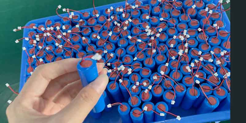
Phase 2: Prototype Development (4–8 weeks)
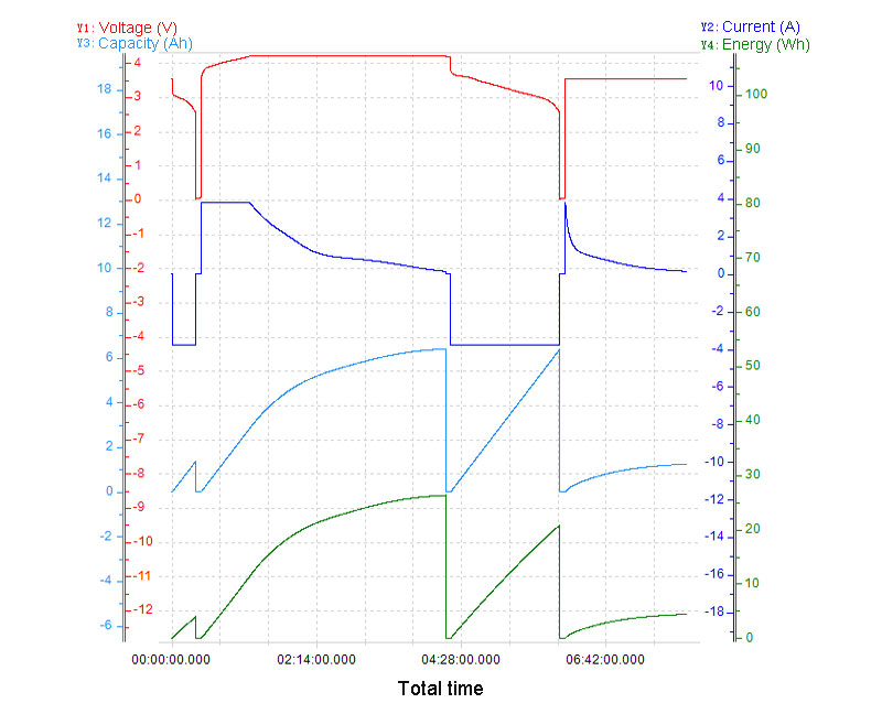
The battery pack prototype is built and validated against the spec. This includes electrical performance testing (capacity, discharge curves, protection function verification), dimensional verification, and BMS communication testing. Typically 3–5 prototypes are produced for the device team to evaluate in actual device hardware.
Phase 3: Design Iteration (2–6 weeks, if needed)
Physical fit adjustments, connector changes, and BMS firmware tuning happen here. For medical applications, changes at this stage need to be documented because they affect the certification test object. Changes after certification testing restart the test process for affected tests. This is the stage-gate discipline that medical battery development requires.
Phase 4: Certification Testing (8–16 weeks)
UN38.3 and IEC 62133 testing are conducted at an accredited third-party laboratory. UN38.3 typically takes 4–6 weeks. IEC 62133 takes 6–10 weeks. These can be run in parallel if the test lab schedule allows. No configuration changes should occur during the test period; any change requires re-test of the affected protocols.
Phase 5: Production Qualification and Supply (4–8 weeks after certification)
First production batch is built, inspected, and released. For medical device OEM customers, this typically includes a First Article Inspection (FAI) and agreement on ongoing incoming inspection criteria.
Total timeline from first technical conversation to certified production sample: typically 6 to 9 months. Device teams that start the battery development conversation early — before the mechanical design is locked — consistently have better outcomes than those who treat the battery as a late-stage procurement item.
Full Specification Reference
| Parameter | Specification |
| Cell | Li-ion 18650, 2000mAh, 3.6V nominal |
| Configuration | 7S1P |
| Nominal Voltage | 25.2V |
| Rated Capacity | 2000mAh |
| Energy | 50.4Wh |
| Charge Voltage | 29.4V |
| Charge Method | CC/CV |
| Charge Current | 0.5C–1.0C (1.0–2.0A) |
| Discharge Cut-off Voltage | 21.0V |
| Max Continuous Discharge | 2.0A |
| Peak Discharge (instant) | 6.0A (≤1 second) |
| BMS Protection | Overcharge, over-discharge, overcurrent, short-circuit, temperature |
| BMS Communication | SMBus / UART / I2C (specify at inquiry stage) |
| Pass-through Charging | Supported (power path management required at device level) |
| Dimensions (preliminary) | L 140.5±2.0mm × W 22.5±2.0mm × H 80.5±2.0mm |
| Weight (approx.) | 350g |
| Certifications | UN38.3, IEC 62133-2, CE DoC (others on request) |
| Customizable | Dimensions, connector, BMS comms protocol, labeling, enclosure |
What to Look for in a Medical Battery Supplier
I’m going to be direct here because I think the industry often avoids this conversation. Not every battery supplier is set up to support a medical device development project well. Here are the things that actually matter when evaluating a supplier for a medical battery:
Cell traceability:
- the supplier should be able to provide documentation identifying the cell manufacturer, model, production lot, and test data for every batch. We cannot accept generic cells from undocumented sources in medical applications where traceability is a regulatory requirement.
Certification documentation readiness:
- 3 and IEC 62133 test reports should be available on request for standard configurations, and the supplier should have experience managing third-party lab submissions for custom packs.
NDA process:
- a supplier that hesitates or creates friction around executing an NDA before technical discussions is not a good fit for a medical product development environment. Confidentiality is standard in this industry.
Engineering responsiveness at the proposal stage:
- the quality of the preliminary technical response tells you a lot about what the design process will look like. A supplier who can turn around a well-reasoned preliminary configuration — with dimensions, BMS specs, charge/discharge parameters, and certification pathway comments — has the technical depth the project needs.
Customization capability:
- medical devices rarely fit a standard battery configuration. The supplier needs to be able to adjust dimensions, BMS firmware, communication protocol, and mechanical integration without treating it as an exception to their normal process.
Working With Himax on Medical Battery Development
At Himax, medical battery projects go through a structured development process that starts with a confidential technical review of the device requirements. We have experience with the full certification stack for lithium-ion medical batteries (UN38.3, IEC 62133, CE) and work with accredited third-party laboratories for independent testing.
The Himax medical devices battery page covers our standard and custom configurations for medical applications. For teams working on portable respiratory or oxygen-related devices, the portable oxygen concentrator battery section provides relevant context on how we approach battery development for life-critical portable medical equipment.
Our broader Li-ion battery portfolio — covering cell chemistries, form factors, and configurations beyond the 18650 7S1P design discussed here — is accessible on the Himax Li-ion battery page.
If you’re early in a medical device battery development project and want to understand what your options are before committing to a direction, the most useful starting point is a technical conversation rather than a quote request. You can reach our engineering team directly through the Himax contact page. We’re set up to review your preliminary requirements, respond with a configuration recommendation, and — when you’re ready — execute a mutual NDA to move into detailed technical discussion.
| About the Author
Dawn is a Senior Battery Engineer in Safety & Compliance at Himax Electronics. With extensive experience in UN38.3, IEC 62133, IEC 62619, and CE compliance, she leads safety and certification work for battery solutions in medical, industrial, and portable electronic applications. She has supported battery development projects from initial technical review through third-party certification and first production release. |