Himax - decorating image

Learn the key feature of each Li-ion in a summary table.

The term lithium-ion points to a family of batteries that shares similarities, but the chemistries can vary greatly. Li-cobalt, Li-manganese, NMC and Li-aluminum are similar in that they deliver high capacity and are used in portable applications. Li-phosphate and Li-titanate have lower voltages and have less capacity, but are very durable. These batteries are mainly found in wheeled and stationary uses. Table 1 summarizes the characteristics of major Li-ion batteries.

Chemistry Lithium Cobalt Oxide Lithium Manganese Oxide Lithium Nickel Manganese Oxide Lithium Iron Phosphate Lithium Nickel Cobalt Aluminum Oxide Lithium Titanate Oxide
Short form Li-cobalt Li-manganese NMC Li-phosphate Li-aluminum Li-titanate
Abbreviation LiCoO2
(LCO)
LiMn2O4
(LMO)
LiNiMnCoO(NMC) LiFePO4
(LFP)
LiNiCoAlO2 (NCA) Li2TiO3 (common)
(LTO)
Nominal voltage 3.60V 3.70V (3.80V) 3.60V (3.70V) 3.20, 3.30V 3.60V 2.40V
Full charge 4.20V 4.20V 4.20V (or higher) 3.65V 4.20V 2.85V
Full discharge 3.00V 3.00V 3.00V 2.50V 3.00V 1.80V
Minimal voltage 2.50V 2.50V 2.50V 2.00V 2.50V 1.50V (est.)
Specific Energy 150–200Wh/kg 100–150Wh/kg 150–220Wh/kg 90–120Wh/kg 200-260Wh/kg 70–80Wh/kg
Charge rate 0.7–1C (3h) 0.7–1C (3h) 0.7–1C (3h) 1C (3h) 1C 1C (5C max)
Discharge rate 1C (1h) 1C, 10C possible 1–2C 1C (25C pule) 1C 10C possible
Cycle life (ideal) 500–1000 300–700 1000–2000 1000–2000 500 3,000–7,000
Thermal runaway 150°C (higher when empty) 250°C (higher when empty) 210°C(higher when empty) 270°C (safe at full charge) 150°C (higher when empty) One of safest
Li-ion batteries
Maintenance Keep cool; store partially charged; prevent full charge cycles, use moderate charge and discharge currents
Packaging (typical) 18650, prismatic and pouch cell prismatic 18650, prismatic and pouch cell 26650, prismatic 18650 prismatic
History 1991 (Sony) 1996 2008 1996 1999 2008
Applications Mobile phones, tablets, laptops, cameras Power tools, medical devices, powertrains E-bikes, medical devices, EVs, industrial Stationary with high currents and endurance Medical, industrial,
EV (Tesla)
UPS, EV, solar street lighting
Comments High energy, limited power. Market share has stabilized. High power, less capacity; safer than Li-cobalt; often mixed with NMC to improve performance. High capacity and high power. Market share is increasing. Also NCM, CMN, MNC, MCN Flat discharge voltage, high power low capacity, very safe; elevated self-discharge. Highest capacity with moderate power. Similar to Li-cobalt. Long life, fast charge, wide temperature range and safe. Low capacity, expensive.

Table 1: Summary of most common lithium-ion based batteries.

Himax - Series and Parallel Battery Configurations

Learn how to arrange batteries to increase voltage or gain higher capacity.

Batteries achieve the desired operating voltage by connecting several cells in series; each cell adds its voltage potential to derive at the total terminal voltage. Parallel connection attains higher capacity by adding up the total ampere-hour (Ah).


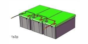
Some packs may consist of a combination of series and parallel connections. Laptop batteries commonly have four 3.6V Li-ion cells in series to achieve a nominal voltage 14.4V and two in parallel to boost the capacity from 2,400mAh to 4,800mAh. Such a configuration is called 4s2p, meaning four cells in series and two in parallel. Insulating foil between the cells prevents the conductive metallic skin from causing an electrical short.


Most battery chemistries lend themselves to series and parallel connection. It is important to use the same battery type with equal voltage and capacity (Ah) and never to mix different makes and sizes. A weaker cell would cause an imbalance. This is especially critical in a series configuration because a battery is only as strong as the weakest link in the chain. An analogy is a chain in which the links represent the cells of a battery connected in series (Figure 1).


Figure 1: Comparing a battery with a chain.

Chain links represent cells in series to increase voltage, doubling a link denotes parallel connection to boost current loading.


A weak cell may not fail immediately but will get exhausted more quickly than the strong ones when on a load. On charge, the low cell fills up before the strong ones because there is less to fill and it remains in over-charge longer than the others. On discharge, the weak cell empties first and gets hammered by the stronger brothers. Cells in multi-packs must be matched, especially when used under heavy loads. (See BU-803a: Cell Mismatch, Balancing).

Single Cell Applications

The single-cell configuration is the simplest battery pack; the cell does not need matching and the protection circuit on a small Li-ion cell can be kept simple. Typical examples are mobile phones and tablets with one 3.60V Li-ion cell. Other uses of a single cell are wall clocks, which typically use a 1.5V alkaline cell, wristwatches and memory backup, most of which are very low power applications.


The nominal cell voltage for a nickel-based battery is 1.2V, alkaline is 1.5V; silver-oxide is 1.6V and lead acid is 2.0V. Primary lithium batteries range between 3.0V and 3.9V. Li-ion is 3.6V; Li-phosphate is 3.2V and Li-titanate is 2.4V.


Li-manganese and other lithium-based systems often use cell voltages of 3.7V and higher. This has less to do with chemistry than promoting a higher watt-hour (Wh), which is made possible with a higher voltage. The argument goes that a low internal cell resistance keeps the voltage high under load. For operational purposes these cells go as 3.6V candidates. (See BU-303 Confusion with Voltages)

Series Connection

Portable equipment needing higher voltages use battery packs with two or more cells connected in series. Figure 2 shows a battery pack with four 3.6V Li-ion cells in series, also known as 4S, to produce 14.4V nominal. In comparison, a six-cell lead acid string with 2V/cell will generate 12V, and four alkaline with 1.5V/cell will give 6V.

Figure 2: Series connection of four cells (4s).

Adding cells in a string increases the voltage; the capacity remains the same.

Courtesy of Cadex

If you need an odd voltage of, say, 9.50 volts, connect five lead acid, eight NiMH or NiCd, or three Li-ion in series. The end battery voltage does not need to be exact as long as it is higher than what the device specifies. A 12V supply might work in lieu of 9.50V. Most battery-operated devices can tolerate some over-voltage; the end-of-discharge voltage must be respected, however.


High voltage batteries keep the conductor size small. Cordless power tools run on 12V and 18V batteries; high-end models use 24V and 36V. Most e-bikes come with 36V Li-ion, some are 48V. The car industry wanted to increase the starter battery from 12V (14V) to 36V, better known as 42V, by placing 18 lead acid cells in series. Logistics of changing the electrical components and arcing problems on mechanical switches derailed the move.


Some mild hybrid cars run on 48V Li-ion and use DC-DC conversion to 12V for the electrical system. Starting the engine is often done by a separate 12V lead acid battery. Early hybrid cars  ran on a 148V battery; electric vehicles are typically 450–500V. Such a battery needs more than 100 Li-ion cells connected in series.


High-voltage batteries require careful cell matching, especially when drawing heavy loads or when operating at cold temperatures. With multiple cells connected in a string, the possibility of one cell failing is real and this would cause a failure. To prevent this from happening, a solid state switch in some large packs bypasses the failing cell to allow continued current flow, albeit at a lower string voltage.


Cell matching is a challenge when replacing a faulty cell in an aging pack. A new cell has a higher capacity than the others, causing an imbalance. Welded construction adds to the complexity of the repair, and this is why battery packs are commonly replaced as a unit.


High-voltage batteries in electric vehicles, in which a full replacement would be prohibitive, divide the pack into modules, each consisting of a specific number of cells. If one cell fails, only the affected module is replaced. A slight imbalance might occur if the new module is fitted with new cells. (See BU-910: How to Repair a Battery Pack.)


Figure 3 illustrates a battery pack in which “cell 3” produces only 2.8V instead of the full nominal 3.6V. With depressed operating voltage, this battery reaches the end-of-discharge point sooner than a normal pack. The voltage collapses and the device turns off with a “Low Battery” message.


Figure 3: Series connection with a faulty cell.

Faulty cell 3 lowers the voltage and cuts the equipment off prematurely.

Courtesy of Cadex

Batteries in drones and remote controls for hobbyist requiring high load current often exhibit an unexpected voltage drop if one cell in a string is weak. Drawing maximum current stresses frail cells, leading to a possible crash. Reading the voltage after a charge does not identify this anomaly; examining the cell-balance or checking the capacity with a battery analyzer will.

Tapping into a Series String

There is a common practice to tap into the series string of a lead acid array to obtain a lower voltage. Heavy duty equipment running on a 24V battery bank may need a 12V supply for an auxiliary operation and this voltage is conveniently available at the half-way point.


Tapping is not recommended because it creates a cell imbalance as one side of the battery bank is loaded more than the other. Unless the disparity can be corrected by a special charger, the side effect is a shorter battery life. Here is why:


When charging an imbalanced lead acid battery bank with a regular charger, the undercharged section tends to develop sulfation as the cells never receive a full charge. The high voltage section of the battery that does not receive the extra load tends to get overcharged and this leads to corrosion and loss of water due to gassing. Please note that the charger charging the entire string looks at the average voltage and terminates the charge accordingly.


Tapping is also common on Li-ion and nickel-based batteries and the results are similar to lead acid: reduced cycle life. (See BU-803a: Cell Matching and Balancing.) Newer devices use a DC-DC converter to deliver the correct voltage. Electric and hybrid vehicles, alternatively, use a separate low-voltage battery for the auxiliary system.

Parallel Connection

If higher currents are needed and larger cells are not available or do not fit the design constraint, one or more cells can be connected in parallel. Most battery chemistries allow parallel configurations with little side effect. Figure 4 illustrates four cells connected in parallel in a P4 arrangement. The nominal voltage of the illustrated pack remains at 3.60V, but the capacity (Ah) and runtime are increased fourfold.


Figure 4: Parallel connection of four cells (4p).

With parallel cells, capacity in Ah and runtime increases while the voltage stays the same.

Courtesy of Cadex


A cell that develops high resistance or opens is less critical in a parallel circuit than in a series configuration, but a failing cell will reduce the total load capability. It’s like an engine only firing on three cylinders instead of on all four. An electrical short, on the other hand, is more serious as the faulty cell drains energy from the other cells, causing a fire hazard. Most so-called electrical shorts are mild and manifest themselves as elevated self-discharge.


A total short can occur through reverse polarization or dendrite growth. Large packs often include a fuse that disconnects the failing cell from the parallel circuit if it were to short. Figure 5 illustrates a parallel configuration with one faulty cell.

Figure 5: Parallel/connection with one faulty cell.

A weak cell will not affect the voltage but provide a low runtime due to reduced capacity. A shorted cell could cause excessive heat and become a fire hazard. On larger packs a fuse prevents high current by isolating the cell.

Courtesy of Cadex

Series/parallel Connection

The series/parallel configuration shown in Figure 6 enables design flexibility and achieves the desired voltage and current ratings with a standard cell size. The total power is the sum of voltage times current; a 3.6V (nominal) cell multiplied by 3,400mAh produces 12.24Wh. Four 18650 Energy Cells of 3,400mAh each can be connected in series and parallel as shown to get 7.2V nominal and a total of 48.96Wh. A combination with 8 cells would produce 97.92Wh, the allowable limit for carry on an aircraft or shipped without Class 9 hazardous material. (See BU-704a: Shipping Lithium-based Batteries by Air) The slim cell allows flexible pack design but a protection circuit is needed.


Figure 6: Series/ parallel connection of four cells (2s2p).

This configuration provides maximum design flexibility. Paralleling the cells helps in voltage management.

Courtesy of Cadex


Li-ion lends itself well to series/parallel configurations but the cells need monitoring to stay within voltage and current limits. Integrated circuits (ICs) for various cell combinations are available to supervise up to 13 Li-ion cells. Larger packs need custom circuits, and this applies to e-bike batteries, hybrid cars and the Tesla Model 85 that devours over 7000 18650 cells to make up the 90kWh pack.

Terminology to describe Series and Parallel Connection

The battery industry specifies the number of cells in series first, followed by the cells placed in parallel. An example is 2s2p. With Li-ion, the parallel strings are always made first; the completed parallel units are then placed in series. Li-ion is a voltage based system that lends itself well for parallel formation. Combining several cells into a parallel and then adding the units serially reduces complexity in terms of voltages control for pack protection.


Building series strings first and then placing them in in parallel may be more common with NiCd packs to satisfy the chemical shuttle mechanism that balances charge at the top of charge. “2s2p” is common; white papers have been issued that refer to 2p2s when a serial string is paralleled.

Safety devices in Series and Parallel Connection

Positive Temperature Coefficient Switches (PTC) and Charge Interrupt Devices (CID) protect the battery from overcurrent and excessive pressure. While recommended for safety in a smaller 2- or 3-cell pack with serial and parallel configuration, these protection devices are often being omitted in larger multi-cell batteries, such as those for power tool.


The PTC and CID work as expected to switch of the cell on excessive current and internal cell pressure; however the shutdown occurs in cascade format. While some cells may go offline early, the load current causes excess current on the remaining cells. Such overload condition could lead to a thermal runaway before the remaining safety devices activate.


Some cells have built-in PCT and CID; these protection devices can also be added retroactively. The design engineer must be aware than any safety device is subject to failure. In addition, the PTC induces a small internal resistance that reduces the load current. (See also BU-304b: Making Lithium-ion Safe)

Simple Guidelines for Using Household Primary Batteries

    • Keep the battery contacts clean.  A four-cell configuration has eight contacts and each contact adds resistance (cell to holder and holder to next cell).
    • Never mix batteries;  replace all cells when weak. The overall performance is only as good as the weakest link in the chain.
    • Observe polarity.  A reversed cell subtracts rather than adds to the cell voltage.
    • Remove batteries from the equipment when no longer in use to prevent leakage and corrosion.  This is especially important with zinc-carbon primary cells.
    • Do not store loose cells in a metal box.  Place individual cells in small plastic bags to prevent an electrical short. Do not carry loose cells in your pockets.
    • Keep batteries away from small children.  In addition to being a choking hazard, the current-flow of the battery can ulcerate the stomach wall if swallowed. The battery can also rupture and cause poisoning.  (See BU-703: Health Concerns with Batteries.)
    • Do not recharge non-rechargeable batteries;  hydrogen buildup can lead to an explosion. Perform experimental charging only under supervision.

Simple Guidelines for Using Secondary Batteries

  • Observe polarity when charging a secondary cell. Reversed polarity can cause an electrical short, leading to a hazardous condition.
  • Remove fully charged batteries from the charger. A consumer charger may not apply the correct trickle charge when fully charged and the cell can overheat.
  • Charge only at room temperature.
Himax - Old and New Battery Packaging

Discover familiar battery formats, some of which going back to the late 1800s.

Early batteries of the 1700s and 1800s developed in Europe were mostly encased in glass jars. As batteries grew in size, jars shifted to sealed wooden containers and composite materials. In the 1890s, battery manufacturing spread from Europe to the United States and in 1896 the National Carbon Company successfully produced a standard cell for widespread consumer use. It was the zinc-carbon Columbia Dry Cell Battery producing 1.5 volts and measuring 6 inches in length.

With the move to portability, sealed cylindrical cells emerged that led to standards sizes. The International Electrochemical Commission (IEC), a non-governmental standards organization founded in 1906, developed standards for most rechargeable batteries. In around 1917, the National Institute of Standards and Technology formalized the alphabet nomenclature that is still used today. Table 1 summarizes these historic and current battery sizes.

Size

Dimensions

History

F cell

33 x 91 mm

Introduced in 1896 for lanterns; later used for radios; only available in nickel-cadmium today.

E cell

N/A

Introduced ca. 1905 to power box lanterns and hobby applications. Discontinued ca. 1980.

D cell

34.2 x 61.5mm

Introduced in 1898 for flashlights and radios; still current.
C cell 25.5 x 50mm Introduced ca. 1900 to attain smaller form factor.

Sub-C

22.2 x 42.9mm
16.1mL

Cordless tool battery. Other sizes are ½, 4/5 and 5/4 sub-C lengths. Mostly NiCd.

B cell

20.1 x 56.8mm

Introduced in 1900 for portable lighting, including bicycle lights in Europe; discontinued in in North America in 2001.

A cell

17 x 50mm

Available in NiCd, NiMH and primary lithium; also in 2/3 and 4/5 sizes. Popular in older laptops and hobby applications.

AA cell

14.5 x 50mm

Introduced in 1907 as penlight battery for pocket lights and spy tool in WWI; added to ANSI standard in 1947.

AAA cell

10.5 x 44.5mm

Developed in 1954 to reduce size for Kodak and Polaroid cameras. Added to ANSI standard in 1959.

AAAA cell

8.3 x 42.5mm

Offshoot of 9V, since 1990s; used for laser pointers, LED penlights, computer styli, headphone amplifiers.

4.5V battery

67 x 62
x 22mm

Three cells form a flat pack; short terminal strip is positive, long strip is negative; common in Europe, Russia.

9V battery

48.5 x 26.5
x 17.5mm

Introduced in 1956 for transistor radios; contains six prismatic or AAAA cells. Added to ANSI standard in 1959.

18650

18 x 65mm
16.5mL

Developed in the mid-1990s for lithium-ion; commonly used in laptops, e-bikes, including Tesla EV cars.

26650

26 x 65mm
34.5mL

Larger Li-ion. Some measure 26x70mm sold as 26700. Common chemistry is LiFeO4 for UPS, hobby, automotive.

14500

14x 50mm

Li-ion, similar size to AA. (Observe voltage incompatibility: NiCd/NiMH = 1.2V, alkaline = 1.5V, Li-ion = 3.6V)
21700* 21 x 70mm New (2016), used for the Tesla Model 3 and other applications, made by Panasonic, Samsung, Molicel, etc.
32650 32 x 65mm Primarily in LiFePO4 (Lithium Iron Phosphate)

Table 1: Common old and new battery norms.
*  The 21700 cell is also known as 2170. IEC norm calls for the second zero at the end to denote cylindrical format.

Standardization included primary cells, mostly in zinc-carbon; alkaline emerged only in the early 1960s. With the growing popularity of the sealed nickel-cadmium in the 1950s and 1960s, new sizes appeared, many of which were derived from the “A” and “C” sizes. Beginning in the 1990s, makers of Li-ion departed from conventional sizes and invented their own standards.

A successful standard is the 18650 cylindrical cell. Developed in the early 1990s for lithium-ion, these cells are used in laptops, electric bicycles and even electric vehicles (Tesla). The first two digits of 18650 designate the diameter in millimeters; the next three digits are the length in tenths of millimeters. The 18650 cell is 18mm in diameter and 65.0mm in length.

Other sizes are identified with a similar numbering scheme. For example, a prismatic cell carries the number 564656P. It is 5.6mm thick, 46mm wide and 56mm long. P stands for prismatic. Because of the large variety of chemistries and their diversity within, battery cells do not show the chemistry.

Few popular new standards have immerged since the 18650 appeared in ca. 1991. Several battery manufacturers started experimenting using slightly larger diameters with sizes of 20x70mm, 21x70mm and 22x70mm. Panasonic and Tesla decided on the 21×70, so has Samsung, and other manufacturers followed.  The “2170” is only slightly larger than the 18650 it but has 35% more energy (by volume). This new cell is used in the Tesla Model 3 while Samsung is looking at new applications in laptops, power tools, e-bikes and more. It is said that the best diameters in terms of manufacturability is between 18mm and 26mm and the 2170 sits in between. (The 2170 is also known as the 21700.) The 26650 introduced earlier never became a best-seller.

The 32650 is primarily available in LiFePO4 (Lithium Iron Phosphate) with a nominal voltage of 3.2V/cell and a typical capacity of 5,000mAh. The dimensions are 32x65mm; true sizes may be slightly larger to allow for insulation and labels.

On the prismatic and pouch cell front, new cells are being developed for the electric vehicle (EV) and energy storage systems (ESS). Some of these formats may one day also become readily available similar to the 18650, made in high energy and high power versions, sourced by several manufacturers and sold at a competitive prices. Prismatic and pouch cells currently carry a higher price tag per Wh than the 18650.

The EV and ESS markets advance with two distinct philosophies: The use of a large number of small cells produced by an automated process as low cost, as done by Tesla, versus larger cells in the prismatic and pouch formats at a higher price per Wh for now, as done by other EV manufacturers. We have not seen clear winners of either format; time will tell.

Looking at the batteries in mobile phones and laptops, one sees a departure from established standards. This is due in part to the manufacturers’ inability to agree on a standard, meaning that most consumer devices come with custom-made cells or battery packs. Compact design and market demand are swaying manufacturers to go their own way. High volume with planned obsolescence allows the production of unique sizes in consumer products.

In the early days, a battery was perceived “big” by nature, and this is reflected in the sizing convention. While the “F” nomenclature may have been seen as mid-sized in the late 1800s, our forefathers did not anticipate that a battery resembling a credit card could power computers, phones and cameras. Running out of letters towards the smaller sizes led to the awkward numbering of AA, AAA and AAAA.

Since the introduction of the 9V battery in 1956, no new formats have emerged. Meanwhile portable devices lowered the operating voltages to between 3V and 5V. Switching six cells (6S) in series to attain 9V is expensive to manufacture, and a 3.6V alternative would serve better. This imaginary new pack would have a coding system to prevent charging primaries and select the correct charge algorithm for secondary chemistries.

Starter batteries for vehicles also follow battery norms that are based on the North American BCI, the European DIN and the Japanese JIS standards. These batteries are similar in footprint to allow swapping. Deep-cycle and stationary batteries follow no standardized norms and the replacement packs must be sourced from the original maker. The attempt to standardize electric vehicle batteries may not work and might follow the failed attempt to standardize laptop batteries in the 1990s.

Future Cell Formats

Standardization for Li-ion cell formats is diverse, especially for the electric vehicle. Research teams, including Fraunhofer,* examine and evaluate various formats and the most promising cell types until 2025 will be the pouch and the 21700 cylindrical formats. Looking further, experts predict the large-size prismatic Li-ion cell to domineer in the EV battery market. Meanwhile, Samsung and others bet on the prismatic cell, LG gravitates towards the pouch format and Panasonic is most comfortable with the 18650 and 21700 cylindrical cells.

Large battery systems for ESS, UPS, marine vessels and traction use mostly large format pouch cells stacked with light pressure to prolong longevity and prevent delamination. Thermal management is often done by plates drawing the heat between layers to the outside and liquid cooling.

Himax - Drones

Safety Issues When Using Drones

The most common drone safety issues, next to pilot error are related to battery failures. If you’ve ever experienced battery failure during charging, storage, or operation, then you understand how alarming and potentially dangerous it can be.

Over 200 injuries related to drone battery incidents were reported to the U.S. Consumer Product Safety Commission between 2012 and 2017. The reported incidents involved fire, smoke, and even explosions. It’s likely that countless other incidents went unreported because they didn’t end in an emergency room visit.

In order to ensure battery safety, it’s critical as a commercial drone operator to purchase your batteries and battery management systems from a reputable, safety-minded provider. 

Why Do Drone Batteries Fail? 

While some drone battery failures occur for reasons that no one could predict or discover, most incidents could have been avoided with proper care and maintenance of your battery fleet. To reduce your potential risk drone users should be well-versed in battery safety practices.

Manufacturers are also responsible for the safety of each battery. In order to provide reliable performance and increased safety, reputable battery manufacturers employ high-quality materials and precise manufacturing and quality control processes. When manufacturers cut corners, they reduce overall battery safety. Quality costs money, so when a battery price seems too good to be true, it probably is.  

Choosing Batteries for Drone Safety

Know the Manufacturer

Reputable manufacturers are transparent and provide plenty of information about their company and practices. Research the quality of materials and designs used to manufacture their drone batteries. If you’re considering a discounted battery purchase but can’t find much information about the company that makes it, it’s best to reconsider. Make sure that your supplier is located within the United States, if you need support or have a question, you want to have an English speaking support staff to answer your call.

Focus on Safety Features

In the interests of the bottom line, some manufacturers strip away “expendable” safety features to create budget batteries. You might be tempted by those batteries when you’re browsing online, but be careful – always review the product description carefully and note the safety features listed. You’ll probably need to visit the manufacturer’s website to find a complete list of features and related details. 

Choose the Right Charger

A top-of-the-line drone battery plugged into a low-quality charger will inevitably cause headaches and compromise battery safety. It’s best to choose a “smart” or programmable battery charger. You’re better able to manage your drone batteries when you have important charging data at your disposal. It’s also best to use batteries and chargers produced by the same manufacturer. 

Best Practices for Battery Safety

How to Store

It’s recommended that you drain batteries to 40-60 percent of their full capacity before storing them for more than ten days. If you’re planning to store them for fewer than 10 days, drain them to 60-80 percent of their capacity. Partially draining batteries reduces stress on them and extends their working life. Never store your batteries for more than three months without charging them. 

It’s best to store batteries in a dry location at room temperature. Before tucking those batteries away, inspect them for a puncture, puffing, or other abnormal physical features that indicate an unhealthy battery. 

How to Charge

Most incidents occur while the battery is charging, which is why it’s recommended to charge your drone batteries at a 1C charge rate. To find this rate take the milliamp hour capacity rating of your battery divide it by 1000. For example, a 22,000 millamp battery should be charged at 22amps. Always monitor your batteries during the charging process and only charge your batteries on a non-flammable surface located away from any flammable materials. While battery fires are rare, a damaged battery or incorrect charge settings can cause a battery to swell, expand and worst-case scenario catch fire. Being prepared with a suitable fire extinguisher and ready to react if you see signs of trouble is critical.

How to Operate

How and where you fly your drone can impact its battery life. It’s best to avoid flying in extreme temperatures. Refer to the manufacturer’s instructions for specific information about safe flight temperatures for your drone. The generally accepted rule is to fly within the range of 14 °F to 104 °F for optimal drone safety. 

Using an appropriately sized battery for your drone is critical for overall safety. Using a battery that does not provide enough power for your drone will not only adversely affect battery life but can lead to overheating of the pack and thermal runaway, a dangerous process that devours the battery. Thermal runaway is a heat-induced chemical reaction that intensifies and continues to raise internal temperatures until all the reactive agents within the cell are consumed. 

How to Transport

Secure your batteries with padding during transport to prevent them from hitting against other batteries or objects. Also, make sure that any exposed leads or connectors are protected from arcing or shorting. Cover with tape or use specifically designed covers to avoid issues.  You can purchase cases and backpacks designed specifically for this purpose. If you’re taking them with you on a plane, remember to pack your drone and batteries in your carry-on baggage and review the current FAA rules for batteries. Regulations for transportation of batteries are also subject to the carrier by carrier-specific rules. Always check with your airline before you try and fly with your drone or batteries.

Himax Provides Safe, Custom-Designed Batteries for Commercial Use

Himax values safety above their bottom line, which is why they offer custom-designed batteries that are produced with superior materials and high-tech safety features. 

Custom-Designed Lithium-Ion Batteries for OEM Applications

Himax’s custom-designed batteries were created for professional, commercial, and industrial use. Their robust composition will withstand the most rigorous, unmanned applications without compromising on energy density and weight. They offer a wide range of custom battery designs, which ensures that you will receive a product that meets your unique and precise requirements. 

Why does custom design matter for drone safety? Himax’s custom-designed batteries accommodate targeted operating temperatures and discharge voltages. When your drone battery is designed with a specific application in mind, it will operate more efficiently and safely in the conditions under which it will actually be used. 

Battery Safety Certifications

Himax products are produced with high-quality materials that ensure durability, extend battery life, and prevent battery failure. Himax can assist with manufacturing to meet and exceed any required safety compliance schemes. We have experience with UN38.3, CE, RoHS, and FCC. We have multiple NRT laboratories that can provide testing services.

Safety Features

Himax’s commercial series of batteries provides the most advanced battery management system (BMS) available on the market. These “smart” batteries include an embedded BMS. This active BMS system helps extend battery life, tracks, and stores critical battery information. The system also allows for additional safety features include real-time fault detection, battery lockout protocol, five LED Indicators, and the ability to capture and store KPIs, which include:

  • Remaining capacity
  • State of charge
  • Cell voltage
  • Pack voltage
  • Current draw
  • Cell temperatures
  • Faults

In addition to careful construction and critical safety features, Himax inspects all products before they leave the factory to ensure each one meets their quality and safety standards.

Himax - Battery-BMS

From: Jack Bayliss

You walk into work one morning and find out that a battery system isn’t working. What happens? How much time will you lose trying to fix it? Getting it back online will probably cost money, but how much?  

When it comes to battery malfunctions, that’s not even the worst-case scenario. What if damage to the battery system causes equipment damage further downstream or even creates a fire?

You consider eventualities like this whenever you integrate a new piece of machinery or develop a new work process, but have you gone through this process when integrating your battery system?  

In this article, we’ll take a look at circuit protection and why it’s so important for industrial batteries. We’ll analyze a few of the different options you have for battery protection systems and how each system can help you to avoid battery damage and dangerous accidents.  

Let’s start with the basics:

Battery-BMS

What Are Battery Protection Systems?

battery protection system is any device that safeguards against battery malfunctions. Some are only effective against basic issues like overcharge or short circuit, while others provide complex monitoring and balancing for an entire battery system. 

What Do They Protect Against?

To really understand why battery protection systems are so important, you need to know what can happen if they’re not in place: 

Short Circuits

These occur when a current takes a shortcut. Electricity always wants to go back to the ground as soon as possible, but a correctly functioning circuit keeps it on the proper track. If the wiring in the circuit malfunctions, the current can escape and go back to the ground another way. That way might involve going through your equipment or one of your workers.

Overcharge

When you put too much charge into a rechargeable battery, that extra energy becomes heat. The temperature of the battery can rise beyond safe limits and reduce the battery’s lifespan.

Over Discharge

Draining too much of the charge from a battery can damage it in several ways, including decreasing the capacity of the battery, causing it to require charging more often, and causing a short circuit within the battery. If a lithium-ion battery lacks a protection system, it is highly prone to these and other malfunctions related to over-discharge.

Overcurrent

Too much current within the circuit can result from a number of malfunctions, including short circuits. If there is enough excess current, it can ignite components of the machinery and cause a fire.

BMS-For-Battery

How Do Battery Protection Systems Help?

Battery protection systems serve to keep the temperature and voltage balanced in your battery. Steady temperatures are critical for optimal battery life, which increases the safety of your operations and reduces your material costs. 

An effective battery protection system will measure the current and temperature in your battery and adjust the circuit to provide protection if levels become unsafe. The process typically involves a thermistor, a ceramic-type semiconductor that decreases in resistance when the temperature of the battery rises. When this happens, it indicates the need for control and simultaneously acts as a battery “first aid.” 

Thermistors work in conjunction with other safety mechanisms. Together, these systems provide the current and temperature control that a battery needs to stay operational. Let’s take a look at some of the most effective options:

Polymeric Positive Temperature Coefficients

The polymeric positive temperature coefficient, or PPTC, helps to balance the circuit against excess energy. Just like a standard fuse, it opens to create high resistance when there is too much current in the system. When the current decreases back to normal levels, it resets.  

Unlike some types of fuses, the PPTC resets itself so that you can still use the battery after the overcurrent is corrected. It simply serves to keep the battery functional until electricity resets back to normal levels.  

PPTCs are most commonly used for nickel batteries. They’re affordable, easy to install, and are compatible with most systems. 

Protection Circuit Modules

Protection circuit modules, or PCMs, protect against overcharge, over-discharge, and excessively fast discharge, all of which can cause an excess of current. In lithium batteries, the PCM usually protects against these situations using a metal-oxide-semiconductor field-effect transistor, or MOSFET.

The MOSFET alters the circuit’s conduction by switching cells on if the voltage falls too quickly or off if the voltage rises to unsafe levels. It keeps the battery running while helping to avoid damage, preserving battery life in the short and long term.  

Battery Management Systems

A battery management system, or BMS, is necessary when you need more precise control over multiple batteries. They provide all of the standard protection involved with simpler systems while monitoring individual cells and the system as a whole.

A BMS can do any of the following:

  • Preserve the life of the battery and keep it safe to use 
  • Report the state of the battery’s charge and capacity
  • Indicate when the battery is in need of replacement
  • Warn the user when the battery needs repair or when the voltage flow is too high 

The most important difference between a BMS and a simpler battery protection system is the ability of the BMS to monitor each cell as well as the full system.    

Individual cell monitoring is critical for battery health because systemwide malfunctions often show themselves at the individual cell level first. By monitoring the voltage in each cell and alerting the user to voltage overages or drops, a BMS can prompt repair of issues such as corrosion or dry-out before they do extensive damage.

In addition to monitoring, a BMS provides safety protection during key processes, including charging and discharging and disconnects the battery in case of failure or safety hazard. It integrates completely with the machine’s software system, allowing the user to get battery alerts as readily as texts or emails.

The Takeaway

Battery protection systems ensure the correct flow of voltage through your batteries, protecting your machinery as well as the health and safety of your personnel.

At Himax, we understand that battery protection is an essential safety function. We offer a variety of products to meet the needs of our industrial clients, and we take pride in our ability to help you select the right product for your business.

If you’re in need of a custom battery or battery charger, contact us today to get started.

Himax - 200ah-12v-Battery-Pack

As technology advances, portable energy solutions are becoming more available and more sophisticated. Highly specialized technologies call for highly specialized batteries.

Custom OEM batteries can help your business operate more efficiently and increase your profits. Himax has many years of experience in designing batteries for Lead-acid replacement, as well as in other industrial and commercial industries. Our custom battery solutions have the power to fulfill your mission-critical requirements and advance your company’s reputation.

How Custom OEM Batteries Benefit Your Brand

Precision Safety

High-quality custom batteries are specifically designed with your product’s application in mind. For instance, your product might be designed for operation in harsh, dirty, or dangerous conditions, in which case you need custom OEM batteries that can operate in rigorous environments for long periods of time. 

Whether it’s strong winds, high altitudes, varying humidity levels, extreme temperatures, or other challenging environmental conditions, you need a custom battery that will power through without failure or malfunction. An experienced company will design and develop custom batteries to suit your product and application while implementing safety features that protect your investment and your reputation.

LiFepo4-battery-pack

Optimal Performance

When you use high-quality, custom OEM batteries, you enhance your product’s performance. Precisely engineered batteries not only minimize safety hazards to people and investments, but they also reduce wasted energy. This increased energy efficiency optimizes your product’s potential, which positions you ahead of the competition. 

Additionally, custom OEM batteries for drones and other high-tech applications can be used as primary power sources or as backup sources for protection in the case of a combustion engine failure or other critical issues. Many custom OEM batteries can also be used in hybrid fuel or battery systems, enhancing performance while providing flexibility.

Increased Endurance


The increased energy efficiency provided by custom OEM batteries also increases your product’s endurance. Drone batteries and other technical-use batteries have come a very long way in terms of longevity, but nothing improves endurance like a custom battery solution. When your product goes farther and lasts longer than the competition’s, it increases your brand’s credibility. That translates to boosted sales. 

Targeted Testing

High-quality, custom OEM batteries undergo rigorous, application-specific testing to guarantee their performance, durability, and strength when used in your product. You’ll want to know how your custom commercial or industrial battery performs while engaged in various applications and under specific conditions. 

Reputable and experienced companies ensure functionality by performing both routine and additional mechanical testing for custom battery designs. Routine tests include component inspection, in-process inspection, and final testing on the completed product. Additional tests should be performed according to your application’s requirements. Reputable companies maintain complete testing data records that can be supplied upon request. 

Direct Support & Transparency

Look for a portable energy solutions company that will provide direct and continual support for your custom OEM batteries. They should be well-staffed, with after-sales support to ensure that you always receive the answers you need, when you need them. 

For your custom OEM battery needs, you’ll want to partner with a company that has access to an extensive, highly vetted network with a strong global presence. Experienced and reputable companies are forthcoming about their supply chains and professional network, so be sure you ask the right questions.

Additionally, any company you partner with should be transparent concerning their security protocols, especially regarding their supply chains in Asian markets. Find out how they intend to keep your sensitive IP projects secure.

Himax Delivers Safe and Professional Custom Battery Solutions

At Himax, we value innovation and integrity. We partner with you to generate, design and implement custom battery solutions and custom charging solutions for your critical operations.

For over 15 years we’ve supplied the energy, aerospace, and automation industries with high-quality, reliable, custom OEM batteries. We’ll work closely with your design team to ensure timely delivery. We’re here to provide support throughout the process and after the sale. 

If you’d like to learn more about how our custom OEM batteries can benefit your product or company, please contact us today.

Himax - High-Energy-Density-Battery

The energy density of batteries can be displayed in two different ways: gravimetric energy density and volumetric energy density.

The gravimetric energy density is the measure of how much energy a battery contains in proportion to its weight. This measurement is typically presented in Watt-hours per kilogram (W-hr / kg). The volumetric energy density, on the other hand, is compared to its volume and is usually expressed in watt-hours per liter (W-hr / L). Generally, we refer to battery energy density as gravimetric ( weight ) energy density, and watt-hour is a measure of electrical energy, equivalent to one hour, one watt of consumption.

In contrast, the power density of a battery is a measure of how fast energy can be delivered, not how much stored energy is available. Energy density is often confused with power density, so it is important to understand the difference between the two.

Calculation formula

The energy density of a battery can be simply calculated using this formula: Nominal Battery Voltage (V) x Rated Battery Capacity (Ah) / Battery Weight (kg) = Specific Energy or Energy Density (Wh / kg).

LiCo and LiFePO4 Batteries’ energy density

Generally speaking, LiCo batteries have an energy density of 150-270 Wh/kg. Their cathode is made up of cobalt oxide and the typical carbon anode with a layered structure that moves lithium-ions from anode to the cathode and back. This battery is popular for its high energy density, and it’s typically used in consumer products such as cell phones and laptops.

LiFe batteries, on the other hand, have an energy density of 100-120 Wh/kg. Although this is lower than LiCo batteries, it is still considered higher in the rechargeable battery category. LiFe batteries use iron phosphate for the cathode and a graphite electrode combined with a metallic backing for the anode. They are ideal for heavy equipment and industrial applications because of their better ability to withstand high and low temperatures.

Conclusion

As far as the single-cell is concerned, the positive and negative materials and production process of the battery will affect the energy density, so it is necessary to develop more reasonable materials and better manufacturing technology to obtain a more efficient battery.

Electric Vehicles Battery

Source:Penn State

Electric Vehicles Battery

Californians do not purchase electric vehicles because they are cool, they buy EVs because they live in a warm climate. Conventional lithium-ion batteries cannot be rapidly charged at temperatures below 50 degrees Fahrenheit, but now a team of Penn State engineers has created a battery that can self-heat, allowing rapid charging regardless of the outside chill.

“Electric vehicles are popular on the west coast because the weather is conducive,” said Xiao-Guang Yang, assistant research professor in mechanical engineering, Penn State. “Once you move them to the east coast or Canada, then there is a tremendous issue. We demonstrated that the batteries can be rapidly charged independently of outside temperature.”

When owners can recharge car batteries in 15 minutes at a charging station, electric vehicle refueling becomes nearly equivalent to gasoline refueling in the time it takes. Assuming that charging stations are liberally placed, drivers can lose their “range anxiety” and drive long distances without worries.

Previously, the researchers developed a battery that could self-heat to avoid below-freezing power drain. Now, the same principle is being applied to batteries to allow 15-minute rapid charging at all temperatures, even as low as minus 45 degrees F.

The self-heating battery uses a thin nickel foil with one end attached to the negative terminal and the other extending outside the cell to create a third terminal. A temperature sensor attached to a switch causes electrons to flow through the nickel foil to complete the circuit when the temperature is below room temperature. This rapidly heats up the nickel foil through resistance heating and warms the inside of the battery. Once the battery’s internal temperature is above room temperature, the switch turns opens and the electric current flows into the battery to rapidly charge it. “One unique feature of our cell is that it will do the heating and then switch to charging automatically,” said Chao-Yang Wang, William E.

Diefenderfer Chair of mechanical engineering, professor of chemical engineering and professor of materials science and engineering, and director of the Electrochemical Engine Center. “Also, the stations already out there do not have to be changed. Control off heating and charging is within the battery, not the chargers.”

The researchers report the results of their prototype testing in this week’s edition of the Proceedings of the National Academy of Sciences. They found that their self-heating battery could withstand 4,500 cycles of 15-minute charging at 32 degrees F with only a 20-percent capacity loss. This provides approximately 280,000 miles of driving and a lifetime of 12.5 years, longer than most warranties.

A conventional battery tested under the same conditions lost 20-percent capacity in 50 charging cycles.

Lithium-ion batteries degrade when rapidly charged under 50 degrees F because, rather than the lithium ions smoothly integrating with the carbon anodes, the lithium deposits in spikes on the anode surface. This lithium plating reduces cell capacity, but also can cause electrical spikes and unsafe battery conditions. Currently, long, slow charging is the only way to avoid lithium plating under 50 degrees F.

Batteries heated above the lithium plating threshold, whether by ambient temperature or by internal heating, will not exhibit lithium plating and will not lose capacity.

“This ubiquitous fast-charging method will also allow manufacturers to use smaller batteries that are lighter and also safer in a vehicle,” said Wang.

High Voltage lifepo4 Battery

High Voltage Battery

LiHV电池的电压

An L-i-H-V battery is a type of Lithium battery that allows for a higher than normal voltage. The “HV” stands for “high voltage” and it has a higher energy density than standard LiPo batteries. Ordinary LiPo batteries have a nominal voltage of 3.7V and a fully charged voltage of 4.2V. LiFePO4 batteries have a nominal voltage of 3.2V and a fully charged voltage of 3.65V. Compared to these, LiHV batteries have a nominal voltage of 3.8V or 3.85V and can reach 4.35V or 4.4V on a full charge.

The characteristics of LiHV battery

With the increasing demand for lithium-ion batteries with higher capacities for electrical equipment, there is a growing expectation for increased energy density of lithium-ion batteries.

While high-voltage batteries have higher energy density and higher discharge platform, the safety performance is lower than that of ordinary batteries. At present, lithium cobalt oxide has been widely studied and applied as a high-voltage anode material. The structure is non-N-A-F-E-O-2 type, which is more suitable for lithium-ion insertion and ejection. The production process is simple, and the electrochemical performance is stable.

Based on the limited space and weight of the electrical power supply, the battery energy can be increased by increasing the battery voltage. For instance, increasing the operating voltage from 4.2v to 4.35v can increase the energy density of the battery up to 16%.

就高压电池和普通电池的放电率而言,高压电池具有更高的放电率和更强的功率。因此,高压电池更适合需要高速率放电的产品和设备。

关于不同容量下的不同电压的图表

下图反映了这三个充满电的电池在4.2V,4.35V和4.4V时的容量差异。

三个充满电的电池在4.2V,4.35V和4.4V时的容量差异。 从格雷普夫出发

从这三个曲线中,您可以看到LiHV电池可以释放出比普通LiPo电池更大的容量,从而为您的设备提供更长的使用寿命。

电池充电提示

值得注意的是,您需要事先知道电池的最大充电电压以防止过度充电。这是因为在过度充电期间释放的氧气和电解质可能会导致正极材料的结构发生变化,从而导致容量损失或剧烈的化学反应,从而缩短电池的寿命和降低性能。在严重的情况下,可能会发生爆炸或火灾。

市场上已经有许多配备了电池管理系统(BMS)的智能电池,可以让我们设置适当的截止电压进行充电,但是还有许多用于FPV 或 RC 车辆的电池 没有BMS,如果没有BMS,则还可以设置充电器的截止电压,以避免过度充电。

Himax - What-Is-The-SEI

The SEI (solid electrolyte interphase) is formed on the surface of the anode from the electrochemical reduction of the electrolyte and plays a crucial role in the long-term cyclability of a lithium-based battery.

Introduction of SEI

During the first charge and discharge of a lithium-ion battery, the electrode material reacts with the electrolyte at the solid-liquid phase interface. After the reaction, a thin film forms on the surface of the electrode material, where Li+ can be embedded and removed freely while electrons cannot. The SEI is about 100-120 nm thick, and it is mainly composed of various inorganic components, such as Lithium Carbonate (Li2CO3), Lithium Fluoride (LiF), Lithium Oxide (Li2O), Lithium Hydroxide (LiOH), as well as some organic components like  Lithium Alkyl Carbonates (ROCO2Li).

Source of SEI

When a lithium-ion battery starts to charge and discharge, the lithium ions are extracted from the active material of the positive electrode. At which point, they enter the electrolyte, penetrate the separator, enter the electrolyte, and finally embed themselves into the layered gap of the negative carbon material.

Electrons then come out of the positive electrode along the outer end loop and enter the negative electrode carbon material. At this point, an oxidation-reduction reaction occurs between the electrons, the solvent in the electrolyte, and the lithium ions. As the thickness of the SEI increases to the point where electrons cannot penetrate it, a passivation layer is formed, which inhibits the continuation of the redox reaction.

SEI’s impact on batteries

The formation of the SEI film has a crucial impact on the performance of electrode materials. On one hand, in the formation of the SEI film, parts of the lithium ions are consumed, which increases the irreversible capacity of batteries and reduces the charge and discharge efficiency of the electrode material.

On the other hand, the SEI is insoluble in organic solvents and can exist in stable conditions in organic electrolyte solutions. Furthermore,  solvent molecules cannot pass through it, thus effectively preventing the co-embedding of the ions and avoiding damage to the electrode material. This greatly improves the cycling performance and service life of the battery.

SEI’s affecting factors

The formation of the SEI is mainly influenced by the following aspects. First, electrolytes (Li salts, solvents, admixtures, etc.), with different compositions will result in different SEI compositions and affect the stability. Next, the formation, that is, the intensity of the first charge and discharges current. High temperature will also reduce the stability of the SEI and affect the battery cycle life. In addition, the thickness of the SEI changes based on the type of negative electrode material.

Conclusion

In-depth research on the SEI with its formation mechanism, structure and stability, and further search for effective ways to improve the performance have been hot topics of research in the electrochemical community.

Copyright ©2024 Shenzhen Himax Electronics Co.,Ltd. | All Rights Reserved