How-to-Store-Batteries(Cover)

Learn about storage temperatures and state-of-charge conditions.

The recommended storage temperature for most batteries is 15°C (59°F); the extreme allowable temperature is –40°C to 50°C (–40°C to 122°F) for most chemistries.

Lead acid

You can store a sealed lead acid battery for up to 2 years. Since all batteries gradually self-discharge over time, it is important to check the voltage and/or specific gravity, and then apply a charge when the battery falls to 70 percent state-of-charge, which reflects 2.07V/cell open circuit or 12.42V for a 12V pack. (The specific gravity at 70 percent charge is roughly 1.218.) Lead acid batteries may have different readings, and it is best to check the manufacturer’s instruction manual. Some battery manufacturer may further let a lead acid to drop to 60 percent before recharge. See BU-903: How to Measure State-of-charge.)

Low charge induces sulfation, an oxidation layer on the negative plate that inhibits current flow. Topping charge and/or cycling may restore some of the capacity losses in the early stages of sulfation. (See BU-804b: Sulfation and How to Prevent it.)

Sulfation may prevent charging small sealed lead acid cells, such as the Cyclone by Hawker, after prolonged storage. These batteries can often be reactivated by applying an elevated voltage. At first, the cell voltage under charge may go up to 5V and draw very little current. Within 2 hours or so, the charging current converts the large sulfate crystals into active material, the cell resistance drops and the charge voltage gradually normalizes. At between 2.10V and 2.40V the cell is able to accept a normal charge. To prevent damage, set the current limit to a very low level. Do not attempt to perform this service if the power supply does not have current limiting. (See BU-405: Charging with a Power Supply.)

Nickel-based

Recommended storage is around 40 percent state-of-charge (SoC). This minimizes age-related capacity loss while keeping the battery operational and allowing for some self-discharge. Nickel-based batteries can be stored in a fully discharged state with no apparent side effect.

Measuring SoC by voltage is difficult on nickel-based batteries. A flat discharge curve, agitation after charge and discharge and temperature affects the voltage. The good news is that the charge level for storage is not critical for this chemistry, so simply apply some charge if the battery is empty and store it in a cool and dry place. With some charge, priming should be quicker than if stored in a totally discharged state.

Nickel-metal-hydride can be stored for 3–5 years. The capacity drop that occurs during storage is partially reversible with priming. Nickel-cadmium stores well. The US Air Force was able to deploy NiCd batteries that had been in storage for 5 years with good recovered capacities after priming. It is believed that priming becomes necessary if the voltage drops below 1V/cell. Primary alkaline and lithium batteries can be stored for up to 10 years with only moderate capacity loss.

Lithium-based

There is virtually no self-discharge below about 4.0V at 20C (68F); storing at 3.7V yields amazing longevity for most Li-ion systems. Finding the exact 40–50 percent SoC level to store Li-ion is not that important. At 40 percent charge, most Li-ion has an OCV of 3.82V/cell at room temperature. To get the correct reading after a charge or discharge, rest the battery for 90 minutes before taking the reading. If this is not practical, overshoot the discharge voltage by 50mV or go 50mV higher on charge. This means discharging to 3.77V/cell or charging to 3.87V/cell at a C-rate of 1C or less. The rubber band effect will settle the voltage at roughly 3.82V. Figure 1 shows the typical discharge voltage of a Li-ion battery.

Discharge OCV

Figure 1: Discharge voltage as a function of state-of-chargeBattery SoC is reflected in OCV. Lithium manganese oxide reads 3.82V at 40% SoC (25°C), and about 3.70V at 30% (shipping requirement). Temperature and previous charge and discharge activities affect the reading. Allow the battery to rest for 90 minutes before taking the reading.

Li-ion cannot dip below 2V/cell for any length of time. Copper shunts form inside the cells that can lead to elevated self-discharge or a partial electrical short. (See BU-802b: Elevated Self-discharge.) If recharged, the cells might become unstable, causing excessive heat or showing other anomalies. Li-ion batteries that have been under stress may function normally but are more sensitive to mechanical abuse. Liability for incorrect handling should go to the user and not the battery manufacturer.

Alkaline

Alkaline and other primary batteries are easy to store. For best results, keep the cells at cool room temperature and at a relative humidity of about 50 percent. Do not freeze alkaline cells, or any battery, as this may change the molecular structure. Some lithium-based primary batteries need special care that is described in BU-106a: Choices of Primary Batteries.

Capacity Loss during Storage

Storage induces two forms of losses: Self-discharge that can be refilled with charging before use, and non-recoverable losses that permanently lower the capacity. Table 2 illustrates the remaining capacities of lithium- and nickel-based batteries after one year of storage at various temperatures. Li-ion has higher losses if stored fully charged rather than at a SoC of 40 percent. (See BU-808: How to Prolong Lithium-based Batteries to study capacity loss in Li-ion.)

Temperature

Lead acid

at full charge

Nickel-based

at any charge

Lithium-ion (Li-cobalt)

40% charge

100% charge

0°C

25°C

40°C

60°C

97%

90%

62%

38%
(after 6 months)

99%

97%

95%

70%

98%

96%

85%

75%

94%

80%

65%

60%
(after 3 months)

Table 2: Estimated recoverable capacity when storing a battery for one year. Elevated temperature hastens permanent capacity loss. Depending on battery type, lithium-ion is also sensitive to charge levels.

Batteries are often exposed to unfavorable temperatures, and leaving a mobile phone or camera on the dashboard of a car or in the hot sun are such examples. Laptops get warm when in use and this increases the battery temperature. Sitting at full charge while plugged into the mains shortens battery life. Elevated temperature also stresses lead- and nickel-based batteries. (See BU-808: How to Prolong Lithium-based Batteries.)

Nickel-metal-hydride can be stored for 3–5 years. The capacity drop that occurs during storage is partially reversible with priming. Nickel-cadmium stores well. The US Air Force was able to deploy NiCd batteries that had been in storage for 5 years with good recovered capacities after priming. It is believed that priming becomes necessary if the voltage drops below 1V/cell. Primary alkaline and lithium batteries can be stored for up to 10 years with only moderate capacity loss.

You can store a sealed lead acid battery for up to 2 years. Since all batteries gradually self-discharge over time, it is important to check the voltage and/or specific gravity, and then apply a charge when the battery falls to 70 percent state-of-charge, which reflects 2.07V/cell open circuit or 12.42V for a 12V pack. (The specific gravity at 70 percent charge is roughly 1.218.) Lead acid batteries may have different readings, and it is best to check the manufacturer’s instruction manual. Some battery manufacturer may further let a lead acid to drop to 60 percent before recharge. Low charge induces sulfation, an oxidation layer on the negative plate that inhibits current flow. Topping charge and/or cycling may restore some of the capacity losses in the early stages of sulfation. (See BU-804b: Sulfation and How to Prevent it.)

Sulfation may prevent charging small sealed lead acid cells, such as the Cyclone by Hawker, after prolonged storage. These batteries can often be reactivated by applying an elevated voltage. At first, the cell voltage under charge may go up to 5V and draw very little current. Within 2 hours or so, the charging current converts the large sulfate crystals into active material, the cell resistance drops and the charge voltage gradually normalizes. At between 2.10V and 2.40V the cell is able to accept a normal charge. To prevent damage, set the current limit to a very low level. Do not attempt to perform this service if the power supply does not have current limiting. (See BU-405: Charging with a Power Supply.)

Alkaline batteries are easy to store. For best results, keep the cells at cool room temperature and at a relative humidity of about 50 percent. Do not freeze alkaline cells, or any battery, as this may change the molecular structure.

AirShip

Li-ion batteries not only live longer when stored partially charged; they are also less volatile in shipment should an anomaly occur. The International Air Transport Association (IATA) and FAA mandate that all removable Li-ion packs be shipped at 30% state-of-charge. (More on BU-704a: Shipping Lithium-based Batteries by Air.) SoC can be estimated by measuring the open circuit voltage of a rested battery. (See also BU-903: How to Measure State-of-charge.)

Relating SoC to voltage can be inaccurate as the voltage curve of Li-ion between 20% to 100% charge is flat, as Figure 1 demonstrates. Temperature also plays a role, so do the active materials used in a cell. Aviation authorities seem less concerned about the exact 30% SoC but the importance of shipping Li-ion below 50% SoC. Larger misgivings are wrong labeling by passing Li-ion as a benign nickel-based chemistry.

To bring Li-ion to 30% SoC, discharge the battery in a device featuring a fuel gauge and terminate the discharge at 30% charge. The Embedded Battery Management System (BMS) does a reasonably good job giving SoC information but the measurements are seldom accurate. A full discharge to “Low Batt” is acceptable as long as the battery receives a charge at destination. Keeping Li-ion in a discharged state for a few months could slip the pack to sleep mode. (See BU-808a: How to Awaken a Sleeping Li-ion.)

Modern chargers feature the “AirShip” program that prepares a Li-ion pack for air shipment by discharging or charging the battery to 30% SoC on command. Typical methods are a full discharge with subsequent recharge to 30% using coulomb counting or advanced Kalman filters. Li-ion batteries built into devices have less stringent SoC requirements than removable packs.

Simple Guidelines for Storing Batteries

  • Primary batteries store well. Alkaline and primary lithium batteries can be stored for 10 years with moderate loss capacity.
  • When storing, remove the battery from the equipment and place in a dry and cool place.
  • Avoid freezing. Batteries freeze more easily if kept in discharged state.
  • Charge lead acid before storing and monitor the voltage or specific gravity frequently; apply a charge if below 2.07V/cell or if SG is below 1.225 (most starter batteries).
  • Nickel-based batteries can be stored for 3–5years, even at zero voltage; prime before use.
  • Lithium-ion must be stored in a charged state, ideally at 40 percent. This prevents the battery from dropping below 2.50V/cell, triggering sleep mode.
  • Discard Li-ion if kept below 2.00/V/cell for more than a week. Also discard if the voltage does not recover normally after storage. (See BU-802b: What does Elevated Self-discharge do?)
CAUTION
When charging an SLA with over-voltage, current limiting must be applied to protect the battery. Always set the current limit to the lowest practical setting and observe the battery voltage and temperature during charge. In case of rupture, leaking electrolyte or any other cause of exposure to the electrolyte, flush with water immediately. If eye exposure occurs, flush with water for 15 minutes and consult a physician immediately.

Wear approved gloves when touching electrolyte, lead and cadmium. On exposure to skin, flush with water immediately.

Himax-Battery-12V-100ah

Learn the key feature of each Li-ion in a summary table.

The term lithium-ion points to a family of batteries that shares similarities, but the chemistries can vary greatly. Li-cobalt, Li-manganese, NMC and Li-aluminum are similar in that they deliver high capacity and are used in portable applications. Li-phosphate and Li-titanate have lower voltages and have less capacity, but are very durable. These batteries are mainly found in wheeled and stationary uses. Table 1 summarizes the characteristics of major Li-ion batteries.

Chemistry Lithium Cobalt Oxide Lithium Manganese Oxide Lithium Nickel Manganese Oxide Lithium Iron Phosphate Lithium Nickel Cobalt Aluminum Oxide Lithium Titanate Oxide
Short form Li-cobalt Li-manganese NMC Li-phosphate Li-aluminum Li-titanate
Abbreviation LiCoO2
(LCO)
LiMn2O4
(LMO)
LiNiMnCoO(NMC) LiFePO4
(LFP)
LiNiCoAlO2 (NCA) Li2TiO3 (common)
(LTO)
Nominal voltage 3.60V 3.70V (3.80V) 3.60V (3.70V) 3.20, 3.30V 3.60V 2.40V
Full charge 4.20V 4.20V 4.20V (or higher) 3.65V 4.20V 2.85V
Full discharge 3.00V 3.00V 3.00V 2.50V 3.00V 1.80V
Minimal voltage 2.50V 2.50V 2.50V 2.00V 2.50V 1.50V (est.)
Specific Energy 150–200Wh/kg 100–150Wh/kg 150–220Wh/kg 90–120Wh/kg 200-260Wh/kg 70–80Wh/kg
Charge rate 0.7–1C (3h) 0.7–1C (3h) 0.7–1C (3h) 1C (3h) 1C 1C (5C max)
Discharge rate 1C (1h) 1C, 10C possible 1–2C 1C (25C pule) 1C 10C possible
Cycle life (ideal) 500–1000 300–700 1000–2000 1000–2000 500 3,000–7,000
Thermal runaway 150°C (higher when empty) 250°C (higher when empty) 210°C(higher when empty) 270°C (safe at full charge) 150°C (higher when empty) One of safest
Li-ion batteries
Maintenance Keep cool; store partially charged; prevent full charge cycles, use moderate charge and discharge currents
Packaging (typical) 18650, prismatic and pouch cell prismatic 18650, prismatic and pouch cell 26650, prismatic 18650 prismatic
History 1991 (Sony) 1996 2008 1996 1999 2008
Applications Mobile phones, tablets, laptops, cameras Power tools, medical devices, powertrains E-bikes, medical devices, EVs, industrial Stationary with high currents and endurance Medical, industrial,
EV (Tesla)
UPS, EV, solar street lighting
Comments High energy, limited power. Market share has stabilized. High power, less capacity; safer than Li-cobalt; often mixed with NMC to improve performance. High capacity and high power. Market share is increasing. Also NCM, CMN, MNC, MCN Flat discharge voltage, high power low capacity, very safe; elevated self-discharge. Highest capacity with moderate power. Similar to Li-cobalt. Long life, fast charge, wide temperature range and safe. Low capacity, expensive.

Table 1: Summary of most common lithium-ion based batteries. Experimental and less common lithium-based batteries are not listed.

Gel Lead Acid Battery(Demo picture)

Learn the unique advantages of lead acid batteries

The early gelled lead acid battery developed in the 1950s by Sonnenschein (Germany) became popular in the 1970s. Mixing sulfuric acid with a silica-gelling agent converts liquid electrolyte into a semi-stiff paste to make the gel maintenance free. The AGM that arrived in the early 1980s offers similar performance to gel but each system offers slightly different characteristics to fill unique market needs. Gel batteries are commonly used in UPS, big and small, while AGM has carved out a market with starter and deep-cycle applications. Gel and AGM batteries are part of the valve-regulated lead acid (VRLA) family to make the traditional flooded lead acid maintenance free.

Energy storage systems (ESS) deployed for frequency regulation and energy buffering use lithium-ion batteries. Unlike lead acid, Li-ion can be rapid charged when excess energy is available. While UPS normally dwells at full-charge and is only discharged occasionally, Li-ion in an ESS can operate at mid-state-of-charge of 40 to 60 percent without inducing sulfation. UPS for standby applications continue to be served by lead acid batteries because of economical cost, ruggedness and superior safety, Li-ion is making inroads into applications that need cycling by delivering the best price per cycle.

A gel battery generally lasts longer than AGM; improved heat transfer to the outside is one reason. (The gel separator moves heat whereas the absorbent glass mat of the AGM acts as insulator.) A further advantage of gel is the dome shaped performance curve that allows the battery to stay in the high performance range during most of its service life before dropping rapidly towards the end of life; AGM, in comparison, fades gradually.

Gel is known for good performance at high ambient temperatures, is less prone to sulfation than other systems, but it needs the correct charge and float voltages. In comparison, AGM is superior at low temperatures with better current delivery because of low internal resistance. The cycle count on gel is said to be larger than AGM and the secret lies in holding more acid due to its design. Because of higher internals resistance, gel batteries are not used for high current applications.

One of the secrets of building a good gel battery lies in the valve construction. Small and economical gel batteries use a valve consisting of EPDM-rubber (EPDM stands for ethylene propylene diene monomer). High quality large gel batteries for use in high and low temperatures use a more elaborate valve design to improve moisture retention.

In terms of suitability and cost, the flooded lead acid is most durable when used in standby operation, but it is also the most expensive and requires maintenance by replenishing water. Gel is cheaper than flooded and is the preferred battery for the UPS installations in communications. AGM comes at a lower cost and is also superior in load capabilities to gel. Both systems have a promising future and will continue to serve for standby applications that require limited deep cycling. Table 1 illustrates the advantages and disadvantages of the gel battery over other lead acid systems.

Advantages Maintenance free; can be mounted sideways; low self-discharge
Long lasting due to its ability to transfer heat to the outside
Performance stays high until the end of life, then drops rapidly
Produces water by combining oxygen and hydrogen
Safe operation and forgiving if abused; less dry-out than AGM
High cycle count, tolerance to abuse and heat
Large variety of battery sizes available
Limitations Higher manufacturing cost than AGM
Sensitive to overcharging (gel is more tolerant than AGM)
Moderate specific energy and load current
Subject to release gases. Ventilation needed
Must be stored in charged condition (less critical than flooded)

Table 1: Advantages and limitations of the gel battery.

Lipo

Intro

Internal resistance ( IR ) is an opposition against the current flow in a lithium-ion battery while it is in operation, and it is an important technical index to measure the performance of a battery.

A large amount of internal resistance turns a part of the energy into heat. This becomes a factor for the increase in battery temperature, which can result in a decrease of the voltage and the shortening of the discharge time, ultimately leaving a serious impact on the battery performance and lifespan.

Ohmic and polarized internal resistance

For Li-ion batteries, there are two components that impact internet resistance: ohmic internal resistance and polarized internal resistance. Ohmic internal resistance is composed of electrode material, electrolytes, diaphragm resistance and contact resistance between the plates, which is related to the size, structure and assembly of the battery. The polarized internal resistance, on the other hand, is the resistance caused by polarization during the electrochemical reaction and also includes the resistance caused by the concentration difference in polarization.

Moreover, the internal resistance is not a constant, and it changes over time during charging and discharging because the composition of the active material, the concentration of the electrolyte and the temperatures are constantly changing. In contrast, the ohmic internal resistance obeys Ohm’s law, and the polarized internal resistance grows with increasing current density.

Influencing factors

Under normal conditions, a battery with small internal resistance has a strong high-current discharge capability, and a battery with large internal resistance has a weak discharge capability. Experience shows that the larger the size of the lithium-ion battery, the smaller the internal resistance, and vice versa.

The size of the internal resistance of the battery will be affected by its own external factors, including raw materials, the production process, and how it is used. It is worth mentioning that the usage and storage temperature greatly affects the activity of the electrochemical material and directly determines the rate of electrochemical reactions and ion movement. The lower the temperature, the slower the ion transport rate and the higher the internal resistance. It also grows in proportions with increasing depth of charge and discharge.

Conclusion

In short, resistance is an important factor in measuring the merits of a battery. As the battery is used, the battery performance will continue to decay and the internal resistance will increase. Therefore, developing low internal-resistance batteries is the key to improving battery performance, which requires our battery manufacturers to continuously optimize and improve product quality to provide users with more stable and efficient energy.


Himax - 130mAh 3.7V custom lithium battery pack

In this issue, we are going to discuss the challenges of Lithium Polymer batteries especially since they suffer from a shorter life if not cared for properly.

Luckily, it’s easy to make sure your Lithium Polymers last as long as they should, allowing you to save on money and the hassle.

LiPO-Battery

When should you charge?

The first challenge in taking care of Lithium Polymers is knowing when to charge them.

In general, Lithium Polymers have a lifespan of somewhere between 300 and 500 charge cycles, from full to empty and back to full again.

But you can help maximize that life by charging before the battery is empty.

Unlike other rechargeable batteries like Ni-cads, Lithium Polymers do not have a memory. So, there is no need to wait until the battery is empty before charging.

In fact, with Lithium Polymer batteries, recharging before the battery is 80% depleted can help prolong the battery life, and is a more efficient way to charge too.

Such as cell phones and laptops, don’t wait until the screen dies before you charge. Charge whenever you get an opportunity.

LiPos are temperature sensitive

You should avoid charging when the battery is below 10ºC/50ºF as the chemical makeup of the battery means it is much less efficient when below that level.

Heat is just as important, hot Lithium Polymer batteries don’t take charge well either, so always ensure they have cooled down after use before charging.

In order to prolong the life of your battery, it is just as important to store them when they’re not being used.

In fact, for Lithium Polymers, this may be the area where most problems occur.

The temptation with batteries is to charge them up before putting them away, so they are ready to go the next time you need them, but for Lithium Polymer batteries without a BMS, this is a disaster.

Causes-of-Lithium-Battery-Swelling

Storage

Thankfully, Lithium Polymer chargers often have a ‘storage’ option for charging, which gives the battery a suitable charge for storage.

Fully charged batteries can expand when stored for an extended period, rendering them unusable, so if you have a storage option, make sure you use it.

Because Lithium Polymer batteries lose less than 1% of charge per month when stored, you will not be in danger of allowing them to discharge too far unless stored for a very long time.

However, it is important to remember that Lithium Polymers do not like being at extremely low voltages from a complete discharge, it can not only shorten life but also damage the battery in some circumstances, so keep an eye on those in storage.

Typical safety mechanism of the 18650 cell cap Demo picture

Batteries can release high energies and the safety requirements for nickel- and lithium-based batteries and cells for portable applications are harmonized under IEC 62133. The standard came into effect in 2012 to reduce the global risk in transporting, storing and operating batteries.


The most basic safety device in a battery is a fuse that opens on high current. Some fuses open permanently and render the battery useless; others are more forgiving and reset. Figure 1 illustrates the top of an 18650 cell for Li-ion with built-in safety features. The resistance of the positive thermal coefficient (PTC) (blue) is low during normal operation and increases when the temperature rises above a critical level to reduce current flow. The PTC is reversible and returns to high conductivity when the temperature normalizes.


The current interrupt device (CID) is a fuse-type device that cuts off the electrical circuit permanently when triggered by excessive cell pressure, high temperature, or high voltage, depending on design. In Figure 1, the CID operates by pressure. When the internal pressure increases to about 1,000kPa, the scored top disk (orange) breaks, separates from the metallic foil (brown) and disconnects the current flow. This also allows gas to vent.


The last safety device is the vent that releases gas during an anomaly and can be resealed. However, the pressure of a disintegrating cell can be so large that the gases are unable to escape in an orderly way and venting with flame occurs. In some cases the top of the cell escapes like a bullet from a shotgun. Similar to a nuclear meltdown that cannot be stopped once in progress; a Li-ion battery once in disintegration should be allowed to burn out in a safe place with ventilation.


Figure 1: Typical safety mechanism of the 18650 cell cap.
PTC (blue) increases resistance by heat to reduce electrical current. The effect is reversible.
CID consists of a top disk (orange) that breaks under pressure and permanently disconnects the current flow.
Source: CALCE (Center for Advanced Life Cycle Engineering)

Protection devices have a residual resistance that causes a slight decrease in overall performance due to a resistive voltage drop. Not all cells have built-in protections and the responsibility for safety in its absence falls to the Battery Management System (BMS).

Further layers of safeguards can include solid-state switches in a circuit that is attached to the battery pack to measure current and voltage and disconnect the circuit if the values are too high. Protection circuits for Li-ion packs are mandatory. (See BU-304b: Making Lithium-ion Safe.)

More information on why batteries fail, what the user can do when a battery overheats and simple guidelines using Lithium-ion Batteries are described in BU-304a: Safety Concerns with Li-ion.


Intrinsically Safe Batteries

Safety is vitally important when using electronic devices in hazardous areas. Intrinsic safety (IS) ensures harmless operation in areas where an electric spark could ignite flammable gas or dust. Hazardous areas include oil refineries, chemical plants, grain elevators and textile mills.

All electronic devices entering a hazardous area must be intrinsically safe. This includes two-way radios, mobile phones, laptops, cameras, flashlights, gas detectors, test devices and medical instruments, even when powered with primary AA and AAA cells. Intrinsically safe devices and batteries contain protection circuits that prevent excessive currents that could lead to high heat, sparks and explosion. The hazard levels are subdivided into these four disciplines.

1. Types of Hazardous Materials present

  • Class I        Flammable gases, vapors or liquids in petroleum refineries, utility gas plants
  • Class II       Combustible dust in grain elevators, coal preparations plants
  • Class III      Ignitable fibers and flyings in textile mills, wood processing creating sawdust, etc.

2. Likelihood of Hazardous Materials present

  • Division I        Hazardous materials can exist in ignitable concentrations
  • Division II       Hazardous materials will not likely exist in ignitable concentrations

3. Potency of Hazardous Material (Groups from A to G)

A hazardous material is given a designation of: Acetylene (A), hydrogen (B), ethylene (C), propane, gasoline, etc. (D), metal dust (E), coal dust  (F) and grain dust (G).

4. Temperature Codes (from T1 to T6)

The explosion danger of gases or combustible dust is affected by surface temperature. T1 is a hot 450ºC (842ºF); T6 is a moderate 85ºC (185ºF). All other temperatures fall in between.

Intrinsic safety requirements vary from country to country. North America has the Factory Mutual Research Corporation, Underwriters Laboratories (UL) and Canadian Standards Association (CSA); Europe has the ATEX directive; while other countries follow the IECEx standards. Many countries recognize harmonized IEC 60079.

Difference chart of charging time of old and new lithium batteries

Battery users often ask: “Why does an old Li-ion lake so long to charge?” Indeed, when Li-ion gets older, the battery takes its time to charge even if there is little to fill. We call this the “old-man syndrome.” Figure 1 illustrates the charge time of a new Li-ion with a capacity of 100 percent against an aged pack delivering only 82 percent. Both take roughly 150 minutes to charge.

aged-vs-new-capacity

Figure 1:   New and aged Li-ion batteries are charged.

Both packs take roughly 150 minutes to charge. The new pack charges to 1,400mAh (100%) while the aged one only goes to 1,150mAh (82%).
Courtesy: Cadex Electronics Inc.

When charging Li-ion, the voltage shoots up similar to lifting a weight with a rubber band. The new pack as demonstrated in Figure 2 is “hungrier” and can take on more “food” before reaching the 4.20V/cell voltage limit compared to the aged Li-ion that hits V Limit in Stage 1 after only about 60 minutes. In terms of a rubber band analogy, the new battery has less slack than to the aged pack and can accept charge longer before going into saturation.

Figure 2: Observing charge times of a new and aged Li-ion in Stage 1.

The new Li-ion takes on full charge for 90 minutes while the aged cell reaches 4.20V/cell in 60 minutes
Courtesy: Cadex Electronics Inc.

Figure 3 demonstrates the different saturation times in Stage 2 as the current trails from the fully regulated current to about 0.05C to trigger ready mode. The trailing on a good battery is short and is prolonged on an aged pack. This explains the longer charge time of an older Li-ion with less capacity. An analogy is a young athlete running a sprint with little or no slow-down towards the end, while the old man gets out of breath and begins walking, prolonging the time to reach the goal.

Figure 3: Observing saturation times of new and aged Li-ion in Stage 2 before switching to ready.

The new cell stays in full-charge longer than the old cell and has a shorter current trail.
Courtesy: Cadex Electronics Inc.

A common aging effect of Li-ion is loss of charge transfer capability. This is caused by the formation of passive materials on the electrodes, which inhibits the flow of free electrons. This reduces the porosity on the electrodes, decreases the surface area, lowers the lower ionic conductivity and raises migration resistance. The aging phenomenon is permanent and cannot be reversed.

The health of a battery is based on these three fundamental attributes:

  • Capacity, the ability to store energy. Capacity is the leading health indicator of a battery
  • Internal resistance, the ability to deliver current
  • Self-discharge, indicator of the mechanical integrity

The charge signature reveals valuable health indicators of Li-ion. A good battery absorbs most of the charge in Stage 1 before reaching 4.20V/cell and the trailing in Stage 2 is short. “Lack of hunger” on a Li-ion can be attributed to a battery being partially charged; exceptionally long trailing times relates to a battery with low capacity, high internal resistance and/or elevated self-discharge.

Algorithms can be developed that compare Stage 1 and Stage 2 based on capacity and state-of-charge. Anomalies, such as low capacity and elevated self-discharge can be identified by setting acceptance thresholds. Cadex is developing chargers with algorithms that will provide diagnostic functions. Such advancement will promote the lone charger into a supervisory position to provide quality assurance in batteries without added logistics.

LiTypes of Lithium-ion

Analyze the pros and cons of other battery systems and learn what the potentials are.

The media promotes wonderful new batteries that promise long runtimes, charge in minutes, are paper-thin and will one day power the electric car. While these experimental batteries produce a voltage, the downsides are seldom mentioned. The typical shortcomings are low load capacity and short cycle life. (See BU-104c: The Octagon Battery.)

As a lemon can be made into a battery, so also has seawater been tried as electrolyte, but the retrieved energy is only good to light an incandescent flashlight for a short time before corrosion buildup renders the battery unusable. Many chemical processes are being tried to generate electricity from diverse metals but only a few promise to surpass today’s lead, nickel and lithium systems.

There is much media hype, and this may be done in part to attract venture capitalists to fund research projects. Few products have incubation periods that are as long as a battery. Although glamorous and promising at first, especially if the battery promises to power the electric vehicle, investment firms are beginning to realize the high development costs, uncertainties and long gestation periods before a return can be realized. Meanwhile, universities continue publishing papers about battery breakthroughs to keep receiving government funding while private companies throw in a paper or two to appease investors and boost their own stock value.

Zinc-air (Primary & Secondary)

Zinc-air batteries generate electrical power by an oxidation process of zinc and oxygen from the air. The cell can produce 1.65V; however, cells with 1.4V and lower voltages achieve a longer lifetime. To activate the battery, the user removes a sealing tab that enables airflow. The battery reaches full operating voltage within 5 seconds. Airflow can control the rate of the reaction somewhat and once turned on, the battery cannot be reverted back to standby mode. Adding a tape to stop the airflow only slows the chemical activity and battery will soon dry out.

The Zinc-air battery shares similarities with the fuel cell (PEMFC) by using oxygen from the air to fuel the positive electrode. It is considered a primary battery and recharging versions for high-power applications have been tried. Recharging occurs by replacing the spent zinc electrodes, which can be in the form of a zinc electrolyte paste. Other zinc-air batteries use zinc pellets.

At 300–400Wh/kg, zinc-air has a high specific energy but the specific power is low. Manufacturing cost is low and in a sealed state, zinc-air has a 2 percent self-discharge per year. The battery is sensitive to hot and cold temperatures and high humidity. Pollution also affects performance; high carbon dioxide content reduces the performance by increasing the internal resistance. Typical applications are hearing aids while large systems operate remote railway signaling and safety lamps at construction sites.

Silver-zinc (Primary & Secondary)

The small silver-based batteries in button cells are typically called silver-oxide and are non-rechargeable; the higher capacity rechargeable versions are referred to as silver-zinc. Both have an open circuit voltage of 1.60 volts. Because of the high cost of silver, these batteries come in either very small sizes where the amount of silver does not contribute significantly to the overall product cost, or they are available in larger sizes for critical applications where the superior performance outweighs any cost considerations.

The primary cells are used for watches, hearing aids and memory backup; the larger rechargeable version is found in submarines, missiles and aerospace applications. Silver-zinc also powers TV cameras needing extra runtime. High cost and short service life locked the silver-zinc out of the commercial market, but it is on the verge of a rebirth with improvements.

The primary cause of failure in the original design was the decaying of the zinc electrode and separator. Cycling developed zinc dendrites that pierced through the separator, causing electrical shorts. In addition, the separator degraded by sitting in the potassium hydroxide electrolyte. This limited the calendar life to about 2 years.

Improvements in the zinc electrode and separator promise a longer service life and a 40 percent higher specific energy than Li-ion. Silver-zinc is safe, has no toxic metals and can be recycled, but the use of silver makes the battery expensive to manufacture.

Reusable Alkaline

The reusable alkaline served as an alternative to disposable batteries. Although fabrication costs were said to be similar to regular alkaline, the consumer did not accept the product.

Recharging alkaline batteries is not new. Ordinary alkaline batteries have been recharged in households for many years. Recharging is most effective if alkaline is discharged to less than 50 percent before recharging. The number of recharges depends on the depth of discharge and is limited to just a few cycles. Battery makers do not endorse this practice for safety reasons; charging ordinary alkaline batteries may generate hydrogen gas that can lead to an explosion.

The reusable alkaline overcomes some of these deficiencies, but a limited cycle count and low capacity on repeat charge are major drawbacks. Longevity is also in direct relationship to the depth of discharge. At a 50 percent depth of discharge, the battery may deliver 50 cycles, but most users run a battery empty before recharging and the manufacturer, including the inventor Karl Kordesch, overestimated the eagerness of the user wanting to recharge early. An additional limitation is its low load current of 400mA, which is only sufficient for flashlights and personal entertainment devices. NiMH in AA and AAA cells has mostly replaced the reusable alkaline.

Typical specific energy of lead-, nickel- and lithium-based batteries

Become familiar with the many different types of lithium-ion batteries.

Lithium-ion is named for its active materials; the words are either written in full or shortened by their chemical symbols. A series of letters and numbers strung together can be hard to remember and even harder to pronounce, and battery chemistries are also identified in abbreviated letters.

For example, lithium cobalt oxide, one of the most common Li-ions, has the chemical symbols LiCoO2 and the abbreviation LCO. For reasons of simplicity, the short form Li-cobalt can also be used for this battery. Cobalt is the main active material that gives this battery character. Other Li-ion chemistries are given similar short-form names. This section lists six of the most common Li-ions. All readings are average estimates at time of writing.

Lithium-ion batteries can be designed for optimal capacity with the drawback of limited loading, slow charging and reduced longevity. An industrial battery may have a moderate Ah rating but the focus in on durability. Specific energy only provides part of battery performance. See also BU-501a: Discharge Characteristics of Li-ion that compares energy cells with power cells.

Lithium Cobalt Oxide(LiCoO2) — LCO

Its high specific energy makes Li-cobalt the popular choice for mobile phones, laptops and digital cameras. The battery consists of a cobalt oxide cathode and a graphite carbon anode. The cathode has a layered structure and during discharge, lithium ions move from the anode to the cathode. The flow reverses on charge. The drawback of Li-cobalt is a relatively short life span, low thermal stability and limited load capabilities (specific power). Figure 1 illustrates the structure.

Li
Figure 1Li-cobalt structure.
The cathode has a layered structure. During discharge the lithium ions move from the anode to the cathode; on charge the flow is from cathode to anode.
Source:  Cadex

The drawback of Li-cobalt is a relatively short life span, low thermal stability and limited load capabilities (specific power). Like other cobalt-blended Li-ion, Li-cobalt has a graphite anode that limits the cycle life by a changing solid electrolyte interface (SEI), thickening on the anode and lithium plating while fast charging and charging at low temperature. Newer systems include nickel, manganese and/or aluminum to improve longevity, loading capabilities and cost.

Li-cobalt should not be charged and discharged at a current higher than its C-rating. This means that an 18650 cell with 2,400mAh can only be charged and discharged at 2,400mA. Forcing a fast charge or applying a load higher than 2,400mA causes overheating and undue stress. For optimal fast charge, the manufacturer recommends a C-rate of 0.8C or about 2,000mA. (See BU-402: What is C-rate). The mandatory battery protection circuit limits the charge and discharge rate to a safe level of about 1C for the Energy Cell.

The hexagonal spider graphic (Figure 2) summarizes the performance of Li-cobalt in terms of specific energy or capacity that relates to runtime; specific power or the ability to deliver high current; safety; performance at hot and cold temperatures; life span reflecting cycle life and longevity; and cost. Other characteristics of interest not shown in the spider webs are toxicity, fast-charge capabilities, self-discharge and shelf life. (See BU-104c: The Octagon Battery – What makes a Battery a Battery).

The Li-cobalt is losing favor to Li-manganese, but especially NMC and NCA because of the high cost of cobalt and improved performance by blending with other active cathode materials. (See description of the NMC and NCA below.)

Li
Figure 2Snapshot of an average Li-cobalt battery.
Li-cobalt excels on high specific energy but offers only moderate performance specific power, safety and life span.
Source:  Cadex

Summary Table

Lithium Cobalt Oxide: LiCoO2 cathode (~60% Co), graphite anode
Short form: LCO or Li-cobalt.Since 1991
Voltages 3.60V nominal; typical operating range 3.0–4.2V/cell
Specific energy (capacity) 150–200Wh/kg. Specialty cells provide up to 240Wh/kg.
Charge (C-rate) 0.7–1C, charges to 4.20V (most cells); 3h charge typical. Charge current above 1C shortens battery life.
Discharge (C-rate) 1C; 2.50V cut off. Discharge current above 1C shortens battery life.
Cycle life 500–1000, related to depth of discharge, load, temperature
Thermal runaway 150°C (302°F). Full charge promotes thermal runaway
Applications Mobile phones, tablets, laptops, cameras
Comments

2019 update:

Very high specific energy, limited specific power. Cobalt is expensive. Serves as Energy Cell. Market share has stabilized.

Early version; no longer relevant.

Table 3: Characteristics of lithium cobalt oxide.

Lithium Manganese Oxide (LiMn2O4) — LMO

Li-ion with manganese spinel was first published in the Materials Research Bulletin in 1983. In 1996, Moli Energy commercialized a Li-ion cell with lithium manganese oxide as cathode material. The architecture forms a three-dimensional spinel structure that improves ion flow on the electrode, which results in lower internal resistance and improved current handling. A further advantage of spinel is high thermal stability and enhanced safety, but the cycle and calendar life are limited.

Low internal cell resistance enables fast charging and high-current discharging. In an 18650 package, Li-manganese can be discharged at currents of 20–30A with moderate heat buildup. It is also possible to apply one-second load pulses of up to 50A. A continuous high load at this current would cause heat buildup and the cell temperature cannot exceed 80°C (176°F). Li-manganese is used for power tools, medical instruments, as well as hybrid and electric vehicles.

Figure 4 illustrates the formation of a three-dimensional crystalline framework on the cathode of a Li-manganese battery. This spinel structure, which is usually composed of diamond shapes connected into a lattice, appears after initial formation.

Li
Figure 4: Li-manganese structure.
The cathode crystalline formation of lithium manganese oxide has a three-dimensional framework structure that appears after initial formation. Spinel provides low resistance but has a more moderate specific energy than cobalt.
Source: Cadex

Li-manganese has a capacity that is roughly one-third lower than Li-cobalt. Design flexibility allows engineers to maximize the battery for either optimal longevity (life span), maximum load current (specific power) or high capacity (specific energy). For example, the long-life version in the 18650 cell has a moderate capacity of only 1,100mAh; the high-capacity version is 1,500mAh.

Figure 5 shows the spider web of a typical Li-manganese battery. The characteristics appear marginal but newer designs have improved in terms of specific power, safety and life span. Pure Li-manganese batteries are no longer common today; they may only be used for special applications.

Figure 5: Snapshot of a pure Li-manganese battery.
Although moderate in overall performance, newer designs of Li-manganese offer improvements in specific power, safety and life span.
Source: Boston Consulting Group

Most Li-manganese batteries blend with lithium nickel manganese cobalt oxide (NMC) to improve the specific energy and prolong the life span. This combination brings out the best in each system, and the LMO (NMC) is chosen for most electric vehicles, such as the Nissan Leaf, Chevy Volt and BMW i3. The LMO part of the battery, which can be about 30 percent, provides high current boost on acceleration; the NMC part gives the long driving range.

Li-ion research gravitates heavily towards combining Li-manganese with cobalt, nickel, manganese and/or aluminum as active cathode material. In some architecture, a small amount of silicon is added to the anode. This provides a 25 percent capacity boost; however, the gain is commonly connected with a shorter cycle life as silicon grows and shrinks with charge and discharge, causing mechanical stress.

These three active metals, as well as the silicon enhancement can conveniently be chosen to enhance the specific energy (capacity), specific power (load capability) or longevity. While consumer batteries go for high capacity, industrial applications require battery systems that have good loading capabilities, deliver a long life and provide safe and dependable service.
Summary Table

Lithium Manganese Oxide: LiMn2O4 cathode. graphite anode
Short form: LMO or Li-manganese (spinel structure)                                                                    Since 1996
Voltages 3.70V (3.80V) nominal; typical operating range 3.0–4.2V/cell
Specific energy (capacity) 100–150Wh/kg
Charge (C-rate) 0.7–1C typical, 3C maximum, charges to 4.20V (most cells)
Discharge (C-rate) 1C; 10C possible with some cells, 30C pulse (5s), 2.50V cut-off
Cycle life 300–700 (related to depth of discharge, temperature)
Thermal runaway 250°C (482°F) typical. High charge promotes thermal runaway
Applications Power tools, medical devices, electric powertrains
Comments

2019 update:

High power but less capacity; safer than Li-cobalt; commonly mixed with NMC to improve performance.

Less relevant now; limited growth potential.

Table 6: Characteristics of Lithium Manganese Oxide.


Lithium Nickel Manganese Cobalt Oxide (LiNiMnCoO2) — NMC

One of the most successful Li-ion systems is a cathode combination of nickel-manganese-cobalt (NMC). Similar to Li-manganese, these systems can be tailored to serve as Energy Cells or Power Cells. For example, NMC in an 18650 cell for moderate load condition has a capacity of about 2,800mAh and can deliver 4A to 5A; NMC in the same cell optimized for specific power has a capacity of only about 2,000mAh but delivers a continuous discharge current of 20A. A silicon-based anode will go to 4,000mAh and higher but at reduced loading capability and shorter cycle life. Silicon added to graphite has the drawback that the anode grows and shrinks with charge and discharge, making the cell mechanically unstable.

The secret of NMC lies in combining nickel and manganese. An analogy of this is table salt in which the main ingredients, sodium and chloride, are toxic on their own but mixing them serves as seasoning salt and food preserver. Nickel is known for its high specific energy but poor stability; manganese has the benefit of forming a spinel structure to achieve low internal resistance but offers a low specific energy. Combining the metals enhances each other strengths.

NMC is the battery of choice for power tools, e-bikes and other electric powertrains. The cathode combination is typically one-third nickel, one-third manganese and one-third cobalt, also known as 1-1-1. Cobalt is expensive and in limited supply. Battery manufacturers are reducing the cobalt content with some compromise in performance. A successful combination is NCM532 with 5 parts nickel, 3 parts cobalt and 2 parts manganese. Other combinations are NMC622 and NMC811. Cobalt stabilizes nickel, a high energy active material

New electrolytes and additives enable charging to 4.4V/cell and higher to boost capacity. Figure 7 demonstrates the characteristics of the NMC.

Figure 7: Snapshot of NMC.
NMC has good overall performance and excels on specific energy. This battery is the preferred candidate for the electric vehicle and has the lowest self-heating rate.
Source: Boston Consulting Group

There is a move towards NMC-blended Li-ion as the system can be built economically and it achieves a good performance. The three active materials of nickel, manganese and cobalt can easily be blended to suit a wide range of applications for automotive and energy storage systems (ESS) that need frequent cycling. The NMC family is growing in its diversity.

Summary Table

Lithium Nickel Manganese Cobalt Oxide: LiNiMnCoO2. cathode, graphite anode
Short form: NMC (NCM, CMN, CNM, MNC, MCN similar with different metal combinations) Since 2008
Voltages 3.60V, 3.70V nominal; typical operating range 3.0–4.2V/cell, or higher
Specific energy (capacity) 150–220Wh/kg
Charge (C-rate) 0.7–1C, charges to 4.20V, some go to 4.30V; 3h charge typical. Charge current above 1C shortens battery life.
Discharge (C-rate) 1C; 2C possible on some cells; 2.50V cut-off
Cycle life 1000–2000 (related to depth of discharge, temperature)
Thermal runaway 210°C (410°F) typical. High charge promotes thermal runaway
Cost ~$420 per kWh (Source: RWTH, Aachen)
Applications E-bikes, medical devices, EVs, industrial
Comments

2019 update:

Provides high capacity and high power. Serves as Hybrid Cell. Favorite chemistry for many uses; market share is increasing.

Leading system; dominant cathode chemistry.

  Table 8: Characteristics of lithium nickel manganese cobalt oxide (NMC).


Lithium Iron Phosphate(LiFePO4) — LFP

In 1996, the University of Texas (and other contributors) discovered phosphate as cathode material for rechargeable lithium batteries. Li-phosphate offers good electrochemical performance with low resistance. This is made possible with nano-scale phosphate cathode material. The key benefits are high current rating and long cycle life, besides good thermal stability, enhanced safety and tolerance if abused.

Li-phosphate is more tolerant to full charge conditions and is less stressed than other lithium-ion systems if kept at high voltage for a prolonged time. (See BU-808: How to Prolong Lithium-based Batteries). As a trade-off, its lower nominal voltage of 3.2V/cell reduces the specific energy below that of cobalt-blended lithium-ion. With most batteries, cold temperature reduces performance and elevated storage temperature shortens the service life, and Li-phosphate is no exception. Li-phosphate has a higher self-discharge than other Li-ion batteries, which can cause balancing issues with aging. This can be mitigated by buying high quality cells and/or using sophisticated control electronics, both of which increase the cost of the pack. Cleanliness in manufacturing is of importance for longevity. There is no tolerance for moisture, lest the battery will only deliver 50 cycles. Figure 9 summarizes the attributes of Li-phosphate.

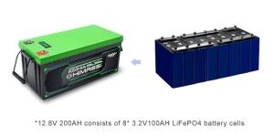
Li-phosphate is often used to replace the lead acid starter battery. Four cells in series produce 12.80V, a similar voltage to six 2V lead acid cells in series. Vehicles charge lead acid to 14.40V (2.40V/cell) and maintain a topping charge. Topping charge is applied to maintain full charge level and prevent sulfation on lead acid batteries.

With four Li-phosphate cells in series, each cell tops at 3.60V, which is the correct full-charge voltage. At this point, the charge should be disconnected but the topping charge continues while driving. Li-phosphate is tolerant to some overcharge; however, keeping the voltage at 14.40V for a prolonged time, as most vehicles do on a long road trip, could stress Li-phosphate. Time will tell how durable Li-Phosphate will be as a lead acid replacement with a regular vehicle charging system. Cold temperature also reduces performance of Li-ion and this could affect the cranking ability in extreme cases.

Figure 9: Snapshot of a typical Li-phosphate battery.
Li-phosphate has excellent safety and long life span but moderate specific energy and elevated self-discharge.
Source:  Cadex

Summary Table

Lithium Iron Phosphate: LiFePO4 cathode, graphite anode
Short form: LFP or Li-phosphate. LIP is also common.                                                                              Since 1996
Voltages 3.20, 3.30V nominal; typical operating range 2.5–3.65V/cell
Specific energy (capacity) 90–120Wh/kg
Charge (C-rate) 1C typical, charges to 3.65V; 3h charge time typical
Discharge (C-rate) 1C, 25C on some cells; 40A pulse (2s); 2.50V cut-off (lower that 2V causes damage)
Cycle life 2000 and higher (related to depth of discharge, temperature)
Thermal runaway 270°C (518°F) Very safe battery even if fully charged
Cost ~$580 per kWh (Source: RWTH, Aachen)
Applications Portable and stationary needing high load currents and endurance
Comments

2019 update:

Very flat voltage discharge curve but low capacity. One of safest
Li-ions. Used for special markets. Elevated self-discharge.Used primarily for energy storage, moderate growth.

Table 10: Characteristics of lithium iron phosphate.

See Lithium Manganese Iron Phosphate (LMFP) for manganese enhanced L-phosphate.

Lithium Nickel Cobalt Aluminum Oxide (LiNiCoAlO2) — NCA

Lithium nickel cobalt aluminum oxide battery, or NCA, has been around since 1999 for special applications. It shares similarities with NMC by offering high specific energy, reasonably good specific power and a long life span. Less flattering are safety and cost. Figure 11 summarizes the six key characteristics. NCA is a further development of lithium nickel oxide; adding aluminum gives the chemistry greater stability.

Figure 11: Snapshot of NCA.
High energy and power densities, as well as good life span, make NCA a candidate for EV powertrains. High cost and marginal safety are negatives.
Source: Cadex

Summary Table

Lithium Nickel Cobalt Aluminum Oxide: LiNiCoAlO2 cathode (~9% Co), graphite anode
Short form: NCA or Li-aluminum.                                                                                                     Since 1999
Voltages 3.60V nominal; typical operating range 3.0–4.2V/cell
Specific energy (capacity) 200-260Wh/kg; 300Wh/kg predictable
Charge (C-rate) 0.7C, charges to 4.20V (most cells), 3h charge typical, fast charge possible with some cells
Discharge (C-rate) 1C typical; 3.00V cut-off; high discharge rate shortens battery life
Cycle life 500 (related to depth of discharge, temperature)
Thermal runaway 150°C (302°F) typical, High charge promotes thermal runaway
Cost ~$350 per kWh (Source: RWTH, Aachen)
Applications Medical devices, industrial, electric powertrain (Tesla)
Comments

2019 update:

Shares similarities with Li-cobalt. Serves as Energy Cell.

Mainly used by Panasonic and Tesla; growth potential.

Table 12: Characteristics of Lithium Nickel Cobalt Aluminum Oxide.

Lithium Titanate (Li2TiO3) — LTO

Batteries with lithium titanate anodes have been known since the 1980s. Li-titanate replaces the graphite in the anode of a typical lithium-ion battery and the material forms into a spinel structure. The cathode can be lithium manganese oxide or NMC. Li-titanate has a nominal cell voltage of 2.40V, can be fast charged and delivers a high discharge current of 10C, or 10 times the rated capacity. The cycle count is said to be higher than that of a regular Li-ion. Li-titanate is safe, has excellent low-temperature discharge characteristics and obtains a capacity of 80 percent at –30°C (–22°F).

LTO (commonly Li4Ti5O12) has advantages over the conventional cobalt-blended Li-ion with graphite anode by attaining zero-strain property, no SEI film formation and no lithium plating when fast charging and charging at low temperature. Thermal stability under high temperature is also better than other Li-ion systems; however, the battery is expensive. At only 65Wh/kg, the specific energy is low, rivalling that of NiCd. Li-titanate charges to 2.80V/cell, and the end of discharge is 1.80V/cell. Figure 13 illustrates the characteristics of the Li-titanate battery. Typical uses are electric powertrains, UPS and solar-powered street lighting.

Figure 13: Snapshot of Li-titanate.
Li-titanate excels in safety, low-temperature performance and life span. Efforts are being made to improve the specific energy and lower cost.
Source: Boston Consulting Group


Summary Table

Lithium Titanate: Cathode can be lithium manganese oxide or NMC; Li2TiO3 (titanate) anode
Short form: LTO or Li-titanate                                              Commercially available since about 2008.
Voltages 2.40V nominal;  typical operating range 1.8–2.85V/cell
Specific energy (capacity) 50–80Wh/kg
Charge (C-rate) 1C typical; 5C maximum, charges to 2.85V
Discharge (C-rate) 10C possible, 30C 5s pulse; 1.80V cut-off  on LCO/LTO
Cycle life 3,000–7,000
Thermal runaway One of safest Li-ion batteries
Cost ~$1,005 per kWh (Source: RWTH, Aachen)
Applications UPS, electric powertrain (Mitsubishi i-MiEV, Honda Fit EV),
solar-powered street lighting
Comments

2019 update:

Long life, fast charge, wide temperature range but low specific energy and expensive. Among safest Li-ion batteries.

Ability to ultra-fast charge; high cost limits to special application.

Table 14: Characteristics of lithium titanate.

Future Batteries

Solid-state Li-ion: High specific energy but poor loading and safety.
Lithium-sulfur: High specific energy but poor cycle life and poor loading
Lithium-air: High specific energy but poor loading, needs clean air to breath and has short life.

Figure 15 compares the specific energy of lead-, nickel- and lithium-based systems. While Li-aluminum (NCA) is the clear winner by storing more capacity than other systems, this only applies to specific energy. In terms of specific power and thermal stability, Li-manganese (LMO) and Li-phosphate (LFP) are superior. Li-titanate (LTO) may have low capacity but this chemistry outlives most other batteries in terms of life span and also has the best cold temperature performance. Moving towards the electric powertrain, safety and cycle life will gain dominance over capacity. (LCO stands for Li-cobalt, the original Li-ion.)

Figure 15: Typical specific energy of lead-, nickel- and lithium-based batteries.
NCA enjoys the highest specific energy; however, manganese and phosphate are superior in terms of specific power and thermal stability. Li-titanate has the best life span.
Courtesy of Cadex

Himax - What Is C-rate?

Observe how the charge and discharge rates are scaled and why it matters.

Charge and discharge rates of a battery are governed by C-rates. The capacity of a battery is commonly rated at 1C, meaning that a fully charged battery rated at 1Ah should provide 1A for one hour. The same battery discharging at 0.5C should provide 500mA for two hours, and at 2C it delivers 2A for 30 minutes. Losses at fast discharges reduce the discharge time and these losses also affect charge times.

A C-rate of 1C is also known as a one-hour discharge; 0.5C or C/2 is a two-hour discharge and 0.2C or C/5 is a 5-hour discharge. Some high-performance batteries can be charged and discharged above 1C with moderate stress. Table 1 illustrates typical times at various C-rates.

C-rate Time Table 1: C-rate and service times when charging and discharging batteries of 1Ah (1,000mAh)


5C 12 min
2C 30 min
1C 1h
0.5C or C/2 2h
0.2C or C/5 5h
0.1C or C/10 10h
0.05C or C/20 20h

The battery capacity, or the amount of energy a battery can hold, can be measured with a battery analyzer.  The analyzer discharges the battery at a calibrated current while measuring the time until the end-of-discharge voltage is reached. For lead acid, the end-of-discharge is typically 1.75V/cell, for NiCd/NiMH 1.0V/cell and for Li-ion 3.0V/cell. If a 1Ah battery provides 1A for one hour, an analyzer displaying the results in percentage of the nominal rating will show 100 percent. If the discharge lasts 30 minutes before reaching the end-of-discharge cut-off voltage, then the battery has a capacity of 50 percent. A new battery is sometimes overrated and can produce more than 100 percent capacity; others are underrated and never reach 100 percent, even after priming.

When discharging a battery with a battery analyzer capable of applying different C rates, a higher C rate will produce a lower capacity reading and vice versa. By discharging the 1Ah battery at the faster 2C-rate, or 2A, the battery should ideally deliver the full capacity in 30 minutes. The sum should be the same since the identical amount of energy is dispensed over a shorter time. In reality, internal losses turn some of the energy into heat and lower the resulting capacity to about 95 percent or less. Discharging the same battery at 0.5C, or 500mA over 2 hours, will likely increase the capacity to above 100 percent.

To obtain a reasonably good capacity reading, manufacturers commonly rate alkaline and lead acid batteries at a very low 0.05C, or a 20-hour discharge. Even at this slow discharge rate, lead acid seldom attains a 100 percent capacity as the batteries are overrated. Manufacturers provide capacity offsets to adjust for the discrepancies if discharged at a higher C rate than specified. Figure 2 illustrates the discharge times of a lead acid battery at various loads expressed in C-rate.

Typical discharge curves of lead acid as a function of C-rate
Figure 2: Typical discharge curves of lead acid as a function of C-rate.
Smaller batteries are rated at a 1C discharge rate. Due to sluggish behavior, lead acid is rated at 0.2C (5h) and 0.05C (20h).

While lead- and nickel-based batteries can be discharged at a high rate, the protection circuit prevents the Li-ion Energy Cell from discharging above 1C. The Power Cell with nickel, manganese and/or phosphate active material can tolerate discharge rates of up to 10C and the current threshold is set higher accordingly.