Himax 12v-batteries-in-parallel

Definition of Series and Parallel Connection of Lithium Batteries

Due to the limited voltage and capacity of the single battery cell, the series and parallel connection is needed in the actual use to obtain higher voltage and capacity, so as to meet the actual power demand of the equipment.

  • Lithium batteries connected in series
    Add the voltage of batteries, capacity remains the same, and internal resistance increases.
  • Lithium batteries connected in paralle
    Constant voltage, added capacity, reduced internal resistance, and extended power supply time.
  • Lithium batteries connected in series and parallel
    3.7V single battery can be assembled into battery pack with a voltage of 3.7*(N)V as required (N: number of single batteries)
    For example, 7.4V, 12V, 24V, 36V, 48V, 60V, 72V, etc.
  • Capacity of Parallel Connection
    2000mAh single battery can be assembled into a battery pack with capacity of 2*(N)Ah as required (N: number of single batteries)
    For example, 4000mAh, 6000mAh, 8000mAh,5Ah10Ah20Ah, 30Ah, 50Ah100Ah, etc.

Lithium Battery Pack

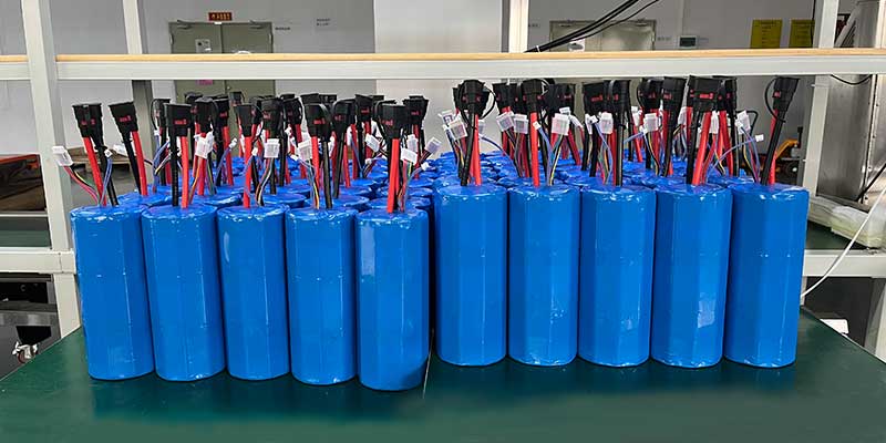
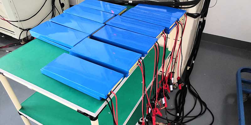
Lithium battery pack technique refers to the processing, assembly and packaging of lithium battery pack. The process of assembling lithium cells together is called PACK, which can be a single battery or a lithium battery pack connected in series or parallel. The lithium battery pack usually consists of a plastic case, PCM, cell, output electrode, bonding sheet, and other insulating tape, double-coating tape, etc.

  • Lithium cell: The core of a finished battery
  • PCM: Protection functions of over charge, over discharge, over current, short circuit, NTC intelligent temperature control.
  • Plastic case: the supporting skeleton of the entire battery; Position and fix the PCM; Carry all other non-case parts and limit.
  • Terminal lead: It can provide a variety of terminal wire charging and discharging interface for a variety of electronic products, energy storage products and backup power.
  • Nickel sheet/bracket: Connection and fixing component of the cell


Lithium Battery Pack Structure

Lithium Battery Series and Parallel Connection

Due to security reasons, lithium ion batteries need an external PCM used for battery monitoring for each battery. It is not recommended to use batteries in parallel. If connect in parallel, make sure the consistency of the battery parameters (capacity, internal resistance, etc.), the other batteries in series need to have consistent parameters, otherwise, the performance of the battery pack can be much worse than the performance of a single cell.

Lithium Battery Series and Parallel Connection

Lithium battery matching criteria
voltage difference ≤ 10 mv, impedance difference ≤ 5 mΩ, capacity difference ≤20mA

The purpose of lithium battery matching is to ensure that every cell in the battery has consistent capacity, voltage and internal impedance, because inconsistent performances will make lithium battery have various parameters during using. Voltage imbalance will happen. After a long run, the battery will overcharge, over discharge, capacity lost, or even fire to explode.

Two Lithium Batteries Connected in Series (7.4V Lithium Battery)

Two Lithium Batteries Connected in Series
model 18650-2S1P 18650-2S1P 18650-2S2P 18650-2S3P
Voltage 7.4V 7.4V 7.4V 7.4V
Capacity 2200/2500/3000mAh 2200/2500/3000mAh 6000mAh 9000mAh
Dimension 18*105mm 18*36*65mm 37*37*66mm 37*55*66mm
Weight 90g 90g 180g 270g

Three Lithium Batteries Connected in Series (11.1V Lithium Battery)

Three Lithium Batteries Connected in Series
Series and Parallel Connection Mode 18650-3S1 P triangle 18650-3S1P in-line 18650-3S2P 18650-3S3P
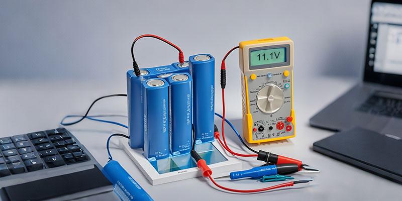
Voltage 11.1V 11.1V 11.1V 11.1V
Capacity 2200/2500/3000mAh 2200/2500/3000mAh 6000mAh 9000mAh
Dimension 66.5*36.6*36.6mm 69.8*55.7*18.8mm 66.8*55.0*40.8mm 60.6*68.0*56.1mm
Weight 155g 158g 285g 425g

Four Lithium Batteries Connected in Series (14.8V Lithium Battery)

Four Lithium Batteries Connected in Series
Series and Parallel Connection Mode 18650-4S1P square 18650-4S1P In-line 18650-4S2P
Voltage 14.8V 14.8V 14.8V
Capacity 2200/2500/3000mAh 2200/2500/3000mAh 6000mAh
Dimension 69.6*37.7*37.7mm 69.3*73.4*17.6mm 70.6*74.2*37.1mm
Weight 181g 191g 371g

Six Lithium Batteries Connected in Series (22.2V Lithium Battery)

Six Lithium Batteries Connected in Series
Series and Parallel Connection Mode 18650-6S1P In-line 18650-6S2P 18650-6S3P
Voltage 25.2V 25.2V 25.2V
Capacity 2000/3000mAh 6000mAh 9000mAh
Dimension 114*72*22mm 114*72*41mm 114*72*60mm
Weight 303g 570g 835g

The length of the plug and lead of the lithium battery pack can be customized according to the customer’s electrical equipment.

Lithium Battery Wire/Terminal

We all know that lithium battery voltage increases after series connection, capacity increases after parallel connection, then how to calculate a lithium battery quantity of series or parallel connection, and how many cells?

Before the calculation, we need to know which cell specification of the battery pack is adopted for the assembly, because different cells have different voltage and capacity. The cell quantity of series and parallel connection required to assemble a specific lithium battery pack varies. The common lithium cell types on the market are: 3.7V LiCoO2, 3.6V ternary, 3.2V LFePO4, 2.4V lithium titanate. The capacity is different because of the cell size, material and manufacturers.

Take 48V 20Ah Lithium Battery Pack for Example

  • Suppose the size of the single cell used is 18650 3.7V 2000mAh
  • Cell quantity of series connection: 48V/3.7V=12.97. That is 13 cells in series.
  • Cell quantity of parallel connection: 20Ah/2Ah=10. That is 10 cells in parallel.

Commonly Used Lithium Battery Connected in series

Nominal Voltage Battery Category Common Quantity of series connection Charging Voltage
12V 3.7V LiCoO2 3S 12.6V
3.2V LiFePO4 4S 14.6V
24V 3.7V LiCoO2 7S 29.4V
3.2V LiFePO4 8S 29.2V
36V 3.7V LiCoO2 10S 42.0V
3.7V LiCoO2 11S 46.2V
3.2V LiFePO4 11S 40.2V
3.2V LiFePO4 12S 43.8V
48V 3.7V LiCoO2 13S 54.6V
3.7V LiCoO2 14S 58.8V
3.2V LiFePO4 15S 58.8V
3.2V LiFePO4 16S 58.8V
60V 3.7V LiCoO2 17S 71.4V
3.2V LiFePO4 20S 73.0V
72V 3.7V LiCoO2 20S 84.0V
3.2V LiFePO4 24S 87.6V

Lithium Battery Assembly Process

18650-3S6P/11.1V/15600mAh Lithium Battery Assembly Process

  • Cell Capacity Grading

    Cell Capacity Grading

    Capacity Difference≤30mAh
    After capacity grading, stay still for 48-72h and then distribute.

  • Voltage Internal Impedance Sorting and Matching

    Voltage Internal Impedance Sorting and Matching

    Voltage Difference≤5mV
    Internal Impedance Difference≤5mΩ 8 cells with similar voltage internal impedance are distributed together.

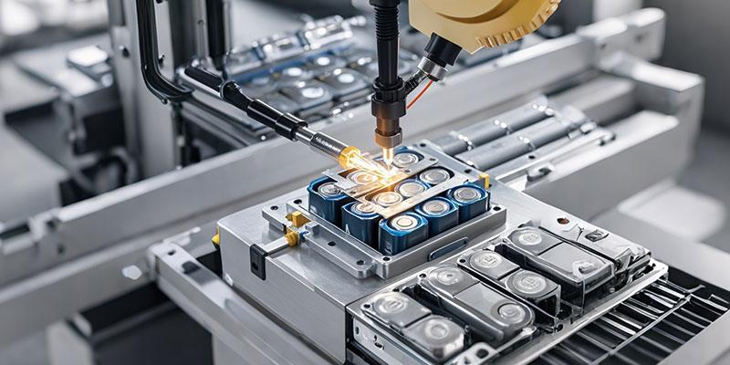
  • Cell Spot Welding

    Cell Spot Welding

    The use of formed nickel strip eliminates the problems of spurious joint, short circuit, low efficiency and uneven current distribution

  • Welded PCM

    Welded PCM

    Make sure that the circuit board has no leakage components, and the components have no defective welding.

  • Battery Insulation

    Battery Insulation

    Paste the fibre, silicone polyester tape for insulation.

  • Battery Pack Aging

    Battery Pack Aging

    For the quality of the battery, improve the stability, safety and service life of the lithium battery.

  • PVC Shrink Film

    PVC Shrink Film

    Position the two ends after heat shrinking,
    then heat shrink the middle part.
    Put PVC film in the middle. No whiten after stretching. No hole.

  • Finished Product Performance Test

    Finished Product Performance Test

    Voltage:10.8~11.7V
    Internal Impedance:≤150mΩ
    Charge-discharge and overcurrent performance test.

  • Battery Code-spurting

    Battery Code-spurting

    Code-spurting cannot be skewed, and it needs legible handwriting

Precautions for Lithium Batteries in Series and Parallel

  • Don’t use batteries with different brands together.
  • Do not use batteries with different voltages together.
  • Do not use different capacities or old and new lithium batteries together.
  • Batteries with different chemical materials cannot be used together, such as nickel metal hydride and lithium batteries.
  • Replace all batteries when electricity is scarce.
  • Use the lithium battery PCM with corresponding parameters.
  • Choose batteries with consistent performance. Generally, distributing of lithium battery cells is required for series and parallel connection. Matching standards: voltage difference≤10mV, impedance difference ≤5mΩ, capacity difference ≤20mA

Due to the consistency issue of lithium batteries, when the same system (such as ternary or lithium iron) is used for series or parallel connection, it is also necessary to select the batteries with the same voltage, internal impedance and capacity for matching. Batteries with different voltage platforms and different internal impedance used in series will cause a certain battery to be fully charged and discharged first in each cycle. If there is a PCM and no fault occurs, the capacity of the whole battery will be reduced. If there is no PCM, the battery will be overcharged or over discharged, which will damage the battery.

Full voltage not available

If different capacities or old and new lithium batteries are used together, there may be leakage, zero voltage and other issues, because during the charging process, capacity differences make some batteries overcharge, some batteries not, while during discharge process, high capacity batteries do not run out of power, but low capacity batteries over discharge. In such a vicious cycle, the batteries will be damaged by leakage or low (zero) voltage.

Full Capacity not available

To assemble lithium batteries, connect them in parallel or in series first?

  • Topological Structure of Lithium Battery Connected in Series and Parallel

The typical connection modes of a lithium battery pack are connecting first in parallel and then in series, first in series and then in parallel, and finally, mixing together.
Lithium battery pack for pure electric buses is usually connected first in parallel and then in series.
Lithium battery pack for power grid energy storage is tend to be connected first in series and then in parallel.

First Parallel and Then Series of Power Battery Module Topological Structure
First Series and Then Parallel of Power Battery Module Topological Structure
First Parallel, Then Series and Parallel Again of Power Battery Module Topological Structure
  • Advantages of Lithium Batteries First Connected in Parallel and Then in Series
    If a lithium battery cell automatically exits, except the capacity reduction, it does not affect parallel connection;
    In parallel connection, a short circuit of a lithium battery cell may cause short circuit due to large current, which is usually avoided by using fuse protection technology.
  • Disadvantages of Lithium Batteries First Connected in Parallel and Then in Series
    If a lithium battery cell automatically exits, except the capacity reduction, it does not affect parallel connection;
    In parallel connection, a short circuit of a lithium battery cell may cause short circuit due to large current, which is usually avoided by using fuse protection technology.
  • Advantages of Lithium Batteries First Connected in Series and Then in Parallel
    First connecting the batteries in series according to the capacity, for example, 1/3 of the whole battery capacity are connected in series, and then connecting the rest in parallel, will reduce the failure probability of high-capacity lithium battery modules. First series and then parallel connection help the consistency of the lithium battery pack.
  • From the perspective of the reliability of the lithium battery connection, the development trend of voltage inconsistency and the influence of performance, the connection mode of first parallel and then series is better than that of first series and then parallel, and the topology structure of first series and then parallel lithium battery is conducive to the detection and management of each lithium battery cell in the system.

Lithium Batteries Charging in Series and Parallel

At present, lithium battery tends to be charged in series, which is mainly due to its simple structure, low cost and easy realization. But as a result of different capacity, internal impedance, aging characteristics and self-discharge performance, when charge lithium battery in series, battery cell with the smallest capacity will be fully charged first, and at this point, the other battery cell is not full of electricity. If continue to charge in series, the fully charged battery cell may be overcharge.

Lithium Battery overcharge will damage the battery performance, and even lead to explosion and injuries, therefore, to prevent battery cell overcharging, lithium battery has equipped with Battery Management System (BMS). The Battery Management System has overcharge protection for every single lithium battery cell, etc. When charging in series, if the voltage of a single lithium battery cell reaches the overcharge protection voltage, the battery management system will cut off the whole series charging circuit and stop charging to prevent the single lithium battery cell from being overcharged, which will cause other lithium batteries unable to be fully charged.

In parallel charging of lithium batteries, each lithium ion battery needs equalizing charge, otherwise, the performance and life of the whole lithium ion battery pack will be affected. Common charging equalization technologies include: constant shunt resistance equalizing charge, on-off shunt resistance equalizing charge, average battery voltage equalizing charge, switch capacitor equalizing charge, step-down converter equalizing charge, inductance equalizing charge, etc.

Several problems need to be paid attention to in parallel charging of lithium batteries:

  • Lithium batteries with and without PCM cannot be charged in parallel. Batteries without PCM can easily be damaged by overcharging.
  • Batteries charged in parallel usually need to remove the built-in PCM of the battery and use a unified battery PCM.
  • If there is no PCM in parallel charging battery, the charging voltage must be limited to 4.2V and 5V charger cannot be used.

After lithium ion batteries connecting in parallel, there will be a charging protection chip for lithium battery charging protection. Lithium battery manufacturers have fully considered the change characteristics of lithium battery in parallel before battery production. The above requirement of current design and choice of batteries are very important, so that users need to follow the instructions of parallel lithium batteries charging step by step, so as to avoid the possible damage for incorrect charge.

  • Special charger must be used for lithium battery, or battery may not reach saturation state, affecting its performance.
  • Before charging the lithium battery, it does not need to discharge completely.
  • Do not keep the charger on the socket for a long time. Remove the charger as soon as the battery fully charged.
  • Batteries shall be taken out of electric appliances that have not been used for a long time and stored after they are fully discharged.
  • Do not plug the anode and cathode of the battery into the opposite direction, otherwise, the battery will swell or burst.
  • Nickel charger and lithium charger cannot be used together.
Himax - What is Equalizing Charge?

Know how to apply an equalize charge and not damage the battery.

Stationary batteries are almost exclusively lead acid and some maintenance is required, one of which is equalizing charge. Applying a periodic equalizing charge brings all cells to similar levels by increasing the voltage to 2.50V/cell, or 10 percent higher than the recommended charge voltage.

An equalizing charge is nothing more than a deliberate overcharge to remove sulfate crystals that build up on the plates over time. Left unchecked, sulfation can reduce the overall capacity of the battery and render the battery unserviceable in extreme cases. An equalizing charge also reverses acid stratification, a condition where acid concentration is greater at the bottom of the battery than at the top.

Himax - What is Equalizing Charge?

Experts recommend equalizing services once a month to once or twice a year. A better method is to apply a fully saturated charge and then compare the specific gravity readings (SG) on the individual cells of a flooded lead acid battery with a hydrometer. Only apply equalization if the SG difference between the cells is 0.030.

During equalizing charge, check the changes in the SG reading every hour and disconnect the charge when the gravity no longer rises. This is the time when no further improvement is possible and a continued charge would have a negative effect on the battery.

The battery must be kept cool and under close observation for unusual heat rise and excessive venting. Some venting is normal and the hydrogen emitted is highly flammable. The battery room must have good ventilation as the hydrogen gas becomes explosive at a concentration of 4 percent.

Equalizing VRLA and other sealed batteries involves guesswork. Observing the differences in cell voltage does not give a conclusive solution and good judgment plays a pivotal role when estimating the frequency and duration of the service. Some manufacturers recommend monthly equalizations for 2–16 hours. Most VRLAs vent at 34kPa (5psi), and repeated venting leads to the depletion of the electrolyte, which can lead to a dry-out condition.

Not all chargers feature equalizing charge. If not available, the service should be performed with a dedicated device.

Himax - How to Awaken a Sleeping Li-ion

Learn what you can do to prevent a Li-ion battery to fall asleep.

Li-ion batteries contain a protection circuit that shields the battery against abuse. This important safeguard also turns the battery off and makes it unusable if over-discharged. Slipping into sleep mode can happen when storing a Li-ion pack in a discharged state for any length of time as self-discharge would gradually deplete the remaining charge. Depending on the manufacturer, the protection circuit of a Li-ion cuts off between 2.2 and 2.9V/cell.

Some battery chargers and analyzers (including Cadex), feature a wake-up feature or “boost” to reactivate and recharge batteries that have fallen asleep. Without this provision, a charger renders these batteries unserviceable and the packs would be discarded. Boost applies a small charge current to activate the protection circuit and if a correct cell voltage can be reached, the charger starts a normal charge. Figure 1 illustrates the “boost” function graphically.

booost1.jpg

Figure 1: Sleep mode of a lithium-ion battery.

Some over-discharged batteries can be “boosted” to life again. Discard the pack if the voltage does not rise to a normal level within a minute while on boost.

Do not boost lithium-based batteries back to life that have dwelled below 1.5V/cell for a week or longer. Copper shunts may have formed inside the cells that can lead to a partial or total electrical short. When recharging, such a cell might become unstable, causing excessive heat or show other anomalies. The Cadex “boost” function halts the charge if the voltage does not rise normally.

When boosting a battery, assure correct polarity. Advanced chargers and battery analyzers will not service a battery if placed in reverse polarity. A sleeping Li-ion does not reveal the voltage, and boosting must be done with awareness. Li-ion is more delicate than other systems and a voltage applied in reverse can cause permanent damage.

Storing lithium-ion batteries presents some uncertainty. On one end, manufacturers recommend keeping them at a state-of-charge of 40–50 percent, and on the other end there is the worry of losing them due to over-discharge. There is ample bandwidth between these criteria and if in doubt, keep the battery at a higher charge in a cool place.

Cadex examined 294 mobile phones batteries that were returned under warranty. The Cadex analyzer restored 91 percent to a capacity of 80 percent and higher; 30 percent were inactive and needed a boost, and 9 percent were non-serviceable. All restored packs were returned to service and performed flawlessly. This study shows the large number of mobile phone batteries that fail due to over-discharging and can be salvaged.


Himax - Cost of Mobile and Renewable Power

Compare battery energy with fossil fuel and other resources

Lifting off in a large airplane is exhilarating. At a full weight of almost 400 tons, the Boeing 747 requires 90 megawatts of power to get airborne. Take-off is the most demanding part of a flight and when reaching cruising altitude the power consumption decreases to roughly half.

Powerful engines were also used to propel the mighty Queen Mary that was launched in 1934. The 81,000-ton ocean liner measuring 300 meters (1,000ft) in length was powered by four steam turbines producing a total power of 160,000hp (120 megawatts). The ship carried 3,000 people and traveled at a speed of 28.5 knots (52km/h). Queen Mary is now a museum in Long Beach, California.

Table 1 illustrates man’s inventiveness in the quest for power by comparing an ox of prehistoric times with newer energy sources made available during the Industrial Revolution to today’s super engines, with seemingly unlimited power.

SINCE TYPE OF POWER SOURCE GENERATED POWER
3000 BC Ox pulling a load 0.5hp 370W
350 BC Vertical waterwheel 3hp 2,230W
1800 Watt’s steam engine 40hp 30kW
1837 Marine steam engine 750hp 560kW
1900 Rail steam engine 12,000hp 8,950kW
1936 Queen Mary ocean liner 160,000hp 120,000kW
1949 Cadillac car 160hp 120kW
1969 Boeing 747 jet airplane 100,000hp 74,600kW
1974 Nuclear power plant 1,520,000hp 1,133,000kW

Table 1: Ancient and modern power sources

Large propulsion systems are only feasible with the internal combustion engines (ICE), and fossil fuel serves as a cheap and plentiful energy resource. Low energy-to-weight ratio in terms of net calorific value (NCV) puts the battery against the mighty ICE like David and Goliath. The battery is the weaker vessel and is sensitive to extreme heat and cold; it also has a relatively short life span.

While fossil fuel delivers an NCV of 12,000Wh/kg, Li-ion provides only between 70Wh/kg and 260Wh/kg depending on chemistry; less with most other systems. Even at a low efficiency of about 30 percent, the ICE outperforms the best battery in terms of energy-to-weight ratio. The battery capacity would need to increase 20-fold before it could compete head-to-head with fossil fuel.

Another limitation of battery propulsion over fossil fuel is fuel by weight. While the weight diminishes when being consumed, the battery carries the same deadweight whether fully charged or empty. This puts limitations on EV driving distance and would make the electric airplane impractical. Furthermore, the ICE delivers full power at freezing temperatures, runs in hot climates, and continues to perform well with advancing age. This is not the case with a battery as each subsequent discharge delivers slightly less energy than the previous cycle.

Power from Primary Batteries

Energy from a non-rechargeable battery is one of the most expensive forms of electrical supply in terms of cost per kilowatt-hours (kWh). Primary batteries are used for low-power applications such as wristwatches, remote controls, electric keys and children’s toys. Military in combat, light beacons and remote repeater stations also use primaries because charging is not practical. Table 2 estimates the capability and cost per kWh of primary batteries.

AAA CELL AA CELL C CELL D CELL 9 VOLT
Capacity (alkaline) 1,150mAh 2,850mAh 7,800mAh 17,000mAh 570mAh
Energy (single cell) 1.725Wh 4.275Wh 11.7Wh 25.5Wh 5.13Wh
Cost per cell (US$) $1.00 $0.75 $2.00 $2.00 $3.00
Cost per kWh (US$) $580 $175 $170 $78 $585

Table 2: Capacity and cost comparison of primary alkaline cells. One-time use makes energy stored in primary batteries expensive; cost decreases with larger battery size.

Power from Secondary Batteries

Electric energy from rechargeable batteries is more economical than with primaries, however, the cost per kWh is not complete without examining the total cost of ownership. This includes cost per cycle, longevity, eventual replacement and disposal. Table 3 compares Lead acid, NiCd, NiMH and Li-ion.

LEAD ACID NICD NIMH LI ION
Specific energy (Wh/kg) 30–50 45–80 60–120 100–250
Cycle life Moderate High High High
Temperature performance Low when cold -50°C to 70°C Reduced when cold Low when cold
Applications UPS with infrequent discharges Rugged, high/low temperature HEV, UPS with frequent discharges EV, UPS with frequent discharges
Cost per kWh ($US)
Load leveling, powertrain
$100-200 $300-600 $300-600 $300–1,000

Table 3: Energy and cost comparison of rechargeable batteries. Although Li-ion is more expensive than Lead acid, the cycle cost may be less. NiCd operates at extreme temperatures, has the best cycle life and accepts ultra-fast charge with little stress.


Power from Other Sources

To reduce the fossil fuel consumption and to lower emissions, governments and the private sector are studying alternate energy sources. Table 4 compares the cost to generate 1kW of power that includes initial investment, fuel consumption, maintenance and eventual replacement.

Fuel type Equipment
to generate 1kW
Life span Cost of fuel
per kWh
Total cost
per kWh
Li-ion
Powertrain
$500/kW (20kW battery
costing $10,000)
2,500h (repl. cost $0.40/kW) $0.20 $0.60
($0.40 + $0.20)
ICE in vehicle $30/kW
($3,000/100kW)
4,000h (repl. cost $0.01/kW) $0.33 $0.34
($0.33 + $0.01)
Fuel cell
– portable
– mobile
– stationary
$3,000–7,500 2,000h
4,000h
40,000h
$0.35
->
->
->
$1.85 – 4.10
$1.10 – 2.25
$0.45 – 0.55
Solar cell $12,000, 5kW system 25 years $0 ~$0.10*
Electricity
electric grid
All inclusive All inclusive $0.20
(average)
$0.20

Table 4: Cost of generating 1kW of energy. Estimations include the initial investment, fuel consumption, maintenance and replacement of the equipment. Grid electricity is lowest.

* Amortization of investment yielding 200 days of 5h/day sun; declining output with age not included.

Power from the electrical utility grid is most cost-effective. Consumers pay between $0.06 and $0.40US per kWh, delivered with no added maintenance cost or the need to replace aging power-generating machinery; the supply is continuous. (The typical daily energy consumption per household in the West is 25kW.)

The supply of cheap electricity changes when energy must be stored in a battery, as is the case with a solar system that is backed up by a battery and in the electric powertrain. High battery cost and a relatively short life can double the electrical cost if supplied by a battery. Gasoline (and equivalent) is the most economical solution for mobility.

The fuel cell is most effective in converting fuel to electricity, but high equipment costs make this power source expensive in terms of cost per kWh. In virtually all applications, power from the fuel cell is considerably more expensive than from conventional methods.

Our bodies also consume energy, and an active man requires 3,500 calories per day to stay fit. This relates to roughly 4,000 watts in a 24-hour day (1 food Calorie* = 1.16 watt-hour). Walking propels a person about 40km (25 miles) per day, and a bicycle increases the distance by a factor of four to 160km (100 miles). Eating two potatoes and a sausage for lunch propels a bicyclist for the afternoon, covering 60km (37 miles, a past-time activity I often do. Not all energy goes to the muscles alone; the brain consumes about 20 percent of our intake. The human body is amazingly efficient in converting food to energy; one would think that the potato and sausage lunch could hardly keep a laptop going for that long. Table 5 provides the stored energies of calories, proteins and fat in watt-hours and joules.

Does the Fuel Cell-powered Vehicle have a Future?(Data trend chart)

Learn about the revival of the fuel cell for transportation


The fuel cell as a propulsion system is in many ways superior to a battery because it needs to carry less energy storage by weight and volume compared to a vehicle propelled by batteries only. Figure 1 illustrates the practical driving range of a vehicle powered by a fuel cell (FC) compared to lead acid, NiMH and Li-ion batteries.

Ess-volume
Figure 1: Driving range as a function of energy storage.

 The logarithmical curves of battery power place limitations in size and weight. The FC has a linear progression and is similar to the ICE vehicle.

Note: 35MPa hydrogen tank refers to 5,000psi pressure; 70MPa is 10,000psi.
Source: International Journal of Hydrogen Energy, 34, 6005-6020 (2009)+

One can clearly see that batteries simply get too heavy when increasing the size to enable greater distances. In this respect, the fuel cell enjoys similar qualities to the internal combustion engine (ICE) in that it can conquer great distances with only the addition of extra fuel.

The weight of fuel is most critical in air transport. Airlines only carry sufficient fuel to safely reach their designation, knowing that the airplane becomes more fuel efficient towards the end of the journey as the weight eases. A study group calculated that if the kerosene in an aircraft were replaced with batteries, the flight would last less than 10 minutes.

Although the fuel cell assumes the duty of the ICE in a vehicle, poor response time and a weak power band make on-board batteries necessary. In this respect, the FC car resembles an electric vehicle with an on-board charger that keeps the batteries charged. This results in short cycles that reduces battery stress over the EV; a propulsion system that bears a resemblance to the HEV.

The FC of a mid-sized car generates around 85kW (114hp) to charge the 18kWh on-board battery and drive the electric motor. On start-up, the vehicle relies fully on the battery; the fuel cell only contributes after reaching a steady state in 5–30 seconds. During the warm-up period, the battery must also deliver power to activate the air compressor and pumps. Once warm, the FC provides enough power for cruising; however, during acceleration, passing and hill-climbing both the FC and battery provide throttle power. Braking delivers kinetic energy to the battery.

Hydrogen costs about twice as much as gasoline, but the higher efficiency of the FC compared to the ICE in converting fuel to energy bring both systems on par. The FC has the added benefit of producing less greenhouse gas than the ICE.

Hydrogen is commonly derived from natural gas. Folks might ask, “Why not burn natural gas directly in the ICE instead of converting it to hydrogen through a reformer and then transforming it to electricity in a fuel cell to feed the electric motors?” The answer is efficiency. Burning natural gas in a combustion turbine to produce electricity has an efficiency factor of only 26–32 percent while a fuel cell is 35–50 percent efficient. That said, the machinery required to support the FC is costlier and requires more maintenance than a simple burning process.

To complicate matters further, building a hydrogen infrastructure is expensive. A refueling station capable of reforming natural gas to hydrogen to support 2,300 vehicles costs over $2 million, or $870 per vehicle. In comparison, a Level 2 charging outlet to charge EVs can easily be installed by connecting to the existing electric grid. The benefit with FC is a quick refill similar to filling a tank with liquid fuel.

Durability and cost are further deterrents for the FC, but improvements are made. The service life of an FC-powered car has doubled from 1,000 hours to 2,000 hours. The target for 2015 is 5,000 hours, or a vehicle life of 240,000km (150,000 miles).

A further challenge is vehicle cost as the fuel cell is more expensive to build than an ICE. As a guideline, an FC vehicle is more expensive than a plug-in hybrid, and the plug-in hybrid is dearer than a gasoline-powered car. With low fuel prices, alternative propulsion systems are difficult to justify on cost alone and the environmental benefits must be considered. Japan is making renewed efforts with FC propulsion to offer an alternative to the ICE and the EV. Toyota plans to phase out the ICE by 2050 and other vehicle makers are observing the trend.

Data trend chart - How to Define Battery Life

Become familiar with battery fade and how the ready light can deceive the user.

Folks have been using rechargeable batteries for over 100 years but this marvelous power source is still poorly understood. The battery is a silent worker that delivers energy until it quits of exhaustion and old age. It is more prone to failure than most other parts in a system. Much is expected but little is given in return. With a shorter life span than the host device, battery replacement becomes an issue, and the “when” and “what if” are not well defined by the device manufacturer. Some batteries are replaced too soon but most stay too long.

A portable system works well when the batteries are new but confidence drops after the first packs need replacing due to capacity fade. In time, the battery fleet becomes a jumble of good and bad batteries, and that’s when the headache begins. Battery management mandates that all batteries in a fleet are kept at an acceptable capacity level. Packs that fall below a given threshold must be replaced to keep system integrity. Battery failure occurs most often on a heavy traffic day or in an emergency when more than normal service is demanded.

Batteries exhibit human-like qualities and need good nutrition. Care begins by operating at room temperate and discharging them at a moderate current. There is some truth as to why batteries cared for by an individual user outperform those in a fleet; studies can back this up.

Charging is generally well understood, but the “ready” light is misconstrued. Ready does not mean “able.” There is no link to battery performance, nor does the green light promise full runtime. All batteries charge fully, even if weak; “ready” simply means that the battery is full.

The capacity a battery can hold diminishes with age and the charge time shortens with nickel-based batteries and in part also with lead acid, but not necessarily with Li-ion. Lower charge transfer capability that inhibits the flow of free electrons prolongs the charge time with aged Li-ion. (See BU-409a: Why do Old Li-ion Batteries Take Long to Charge?)

A short charging time propels faded batteries to the top, disguised as combat ready. System collapse is imminent when workers scramble for freshly charged batteries in an emergency; those that are lit-up may be deadwood. (Note that the charge time of a partially charged battery is also shorter.) Figure 1 shows the “ready” light that is known to lie.

Figure 1: The “ready” light lies. The READY light indicates that the battery is fully charged. This does not mean “able” as there is no link between “ready” and battery performance.

The amount of energy a battery can hold is measured in capacity. Capacity is the leading health indicator that determines runtime and predicts end of battery life when low. A new battery is rated at 100 percent, but few packs in service deliver the full amount: a workable capacity bandwidth is 80–100 percent. As a simple guideline, a battery on a two-way radio having a capacity of 100 percent would typically provide a runtime of 10 hours, 80 percent is 8 hours and 70 percent, 7 hours.

The service life of a battery is specified in number of cycles. Lithium- and nickel-based batteries deliver between 300 and 500 full discharge/charge cycles before the capacity drops below 80 percent.

Cycling is not the only cause of capacity loss; keeping a battery at elevated temperatures also induces stress. A fully charged Li-ion kept at 40°C (104°F) loses about 35 percent of its capacity in a year without being used. ( See BU:808: How to Prolong Lithium-based Batteries ). Ultra-fast chargers and harsh discharging is also harmful. This cuts battery life to half, and hobbyists can attest to this.

Himax - cycle-life-lead-acid(Data trend chart)

Discover what a battery needs to get going and maintain a long life.

In many ways, a battery behaves like a human being. It senses the kindness given and delivers on the care given. It is as if the battery has feelings and returns on the benevolence bestowed. But there are exceptions, as any parent raising a family will know; and the generosity conferred may not always deliver the anticipated returns.

To become a good custodian, you must understand the basic needs of a battery, a subject that is not taught in school. This section teaches what to do when the battery is new, how to feed it the right “food” and what to do when putting the pack aside for a while. Chapter 7 also looks into restrictions when traveling with batteries by air and how to dispose of them when their useful life has passed.

Just as a person’s life expectancy cannot be predicted at birth, neither can we date stamp a battery. Some packs live to a great old age while others die young. Incorrect charging, harsh discharge loads and exposure to heat are the battery’s worst enemies. Although there are ways to protect a battery, the ideal situation is not always attainable. This chapter discusses how to get the most from our batteries.

Priming a New Battery

Not all rechargeable batteries deliver the rated capacity when new, and they require formatting. While this applies to most battery systems, manufacturers of lithium-ion batteries disagree. They say that Li-ion is ready at birth and does not need priming. Although this may be true, users have reported some capacity gains by cycling after a long storage.

“What’s the difference between formatting and priming?” people ask. Both address capacities that are not optimized and can be improved with cycling. Formatting completes the fabrication process that occurs naturally during use when the battery is being cycled. A typical example is lead- and nickel-based batteries that improve with usage until fully formatted. Priming, on the other hand, is a conditioning cycle that is applied as a service to improve battery performance during usage or after prolonged storage. Priming relates mainly to nickel-based batteries.

Lead Acid

Formatting a lead acid battery occurs by applying a charge, followed by a discharge and recharge. This is done at the factory and is completed in the field as part of regular use. Experts advise not to strain a new battery by giving it heavy duty discharges at first but gradually working it in with moderate discharges, like an athlete trains for weight lifting or long-distance running. This, however, may not be possible with a starter battery in a vehicle and other uses. Lead acid typically reaches the full capacity potential after 50 to 100 cycles. Figure 1 illustrates the lifespan of lead acid.

cycle-life-lead-acid

Figure 1: Lifespan of Lead Acid
A new lead acid battery may not by fully formatted and only attains full performance after 50 or more cycles. Formatting occurs during use; deliberate cycling is not recommended as this would wear down the battery unnecessarily.

Deep-cycle batteries are at about 85 percent when new and will increase to 100 percent, or close to full capacity, when fully formatted. There are some outliers that are as low as 65 percent when tested with a battery analyzer. The question is asked, “Will these low-performers recover and stand up to their stronger brothers when formatted?” A seasoned battery expert said that “these batteries will improve somewhat but they are the first to fail.”

The function of a starter battery lies in delivering high load currents to crank the engine, and this attribute is present from the beginning without the need to format and prime. To the surprise of many motorists, the capacity of a starter battery can fade to 30 percent and still crank the engine; however, a further drop may get the driver stranded one morning. See also BU-904: How to Measure Capacity)

Nickel-based

Manufacturers advise to trickle charge a nickel-based battery for 16–24 hours when new and after a long storage. This allows the cells to adjust to each other and to bring them to an equal charge level. A slow charge also helps to redistribute the electrolyte to eliminate dry spots on the separator that might have developed by gravitation.

Nickel-based batteries are not always fully formatted when leaving the factory. Applying several charge/discharge cycles through normal use or with a battery analyzer completes the formatting process. The number of cycles required to attain full capacity differs between cell manufacturers. Quality cells perform to specification after 5–7 cycles, while lower-cost alternatives may need 50 or more cycles to reach acceptable capacity levels.

Lack of formatting causes a problem when the user expects a new battery to work at full capacity out of the box. Organizations using batteries for mission-critical applications should verify the performance through a discharge/charge cycle as part of quality control. The “prime” program of automated battery analyzers (Cadex) applies as many cycles as needed to attain full capacity.

Cycling also restores lost capacity when a nickel-based battery has been stored for a few months. Storage time, state-of-charge and temperature under which the battery is stored govern the ease of recovery. The longer the storage and the warmer the temperature, the more cycles will be required to regain full capacity. Battery analyzers help in the priming functions and assure that the desired capacity has been achieved.

Lithium-ion

Some battery users insist that a passivation layer develops on the cathode of a lithium-ion cell after storage. Also known as interfacial protective film (IPF), this layer is said to restrict ion flow, cause an increase in internal resistance and in the worst case, lead to lithium plating. Charging, and more effectively cycling, is known to dissolve the layer and some battery users claim to have gained extra runtime after the second or third cycle on a smartphone, albeit by a small amount.

Scientists do not fully understand the nature of this layer, and the few published resources on this subject only speculate that performance restoration with cycling is connected to the removal of the passivation layer. Some scientists outright deny the existence of the IPF, saying that the idea is highly speculative and inconsistent with existing studies. Whatever the outcome on the passivation of Li-ion may be, there is no parallel to the “memory” effect with NiCd batteries that require periodic cycling to prevent capacity loss. The symptoms may appear similar but the mechanics are different. Nor can the effect be compared to sulfation of lead acid batteries.

A well-known layer that builds up on the anode is the solid electrolyte solid electrolyte interface (SEI). SEI is an electrical insulation but has sufficient ionic conductivity to allow the battery to function normally. While the SEI layer lowers the capacity, it also protects the battery. Without SEI, Li-ion might not get the longevity that it has. (See BU-307: How does Electrolyte Work?)

The SEI layer develops as part of a formation process and manufacturers take great care to do this right, as a batched job can cause permanent capacity loss and a rise in internal resistance. The process includes several cycles, float charges at elevated temperatures and rest periods that can take many weeks to complete. This formation period also provides quality control and assists in cell matching, as well as observing self-discharge by measuring the cell voltage after a rest. High self-discharge hints to impurity as part of a potential manufacturing defect.

Electrolyte oxidation (EO) also occurs on the cathode. This causes a permanent capacity loss and increases the internal resistance. No remedy exists to remove the layer once formed but electrolyte additives lessen the impact. Keeping Li-ion at a voltage above 4.10V/cell while at an elevated temperature promotes electrolyte oxidation. Field observation shows that the combination of heat and high voltage can stress Li-ion more than harsh cycling.

Lithium-ion is a very clean system that does not need additional priming once it leaves the factory, nor does it require the level of maintenance that nickel-based batteries do. Additional formatting makes little difference because the maximum capacity is available right from the beginning, (the exception may be a small capacity gain after a long storage). A full discharge does not improve the capacity once the battery has faded — a low capacity signals the end of life. A discharge/charge may calibrate a “smart” battery but this does little to improve the chemical battery. (See BU-601: Inner Working of a Smart Battery.) Instructions recommending charging a new Li-ion for 8 hours are written off as “old school,” a left-over from the old nickel battery days.

Non-rechargeable Lithium

Primary lithium batteries, such as lithium-thionyl chloride (LTC), benefit from passivation in storage. Passivation is a thin layer that forms as part of a reaction between the electrolyte, the lithium anode and the carbon-based cathode. (Note that the anode of a primary lithium battery is lithium and the cathode is graphite, the reverse of Li-ion.)

Without this layer, most lithium batteries could not function because the lithium would cause a rapid self-discharge and degrade the battery quickly. Battery scientists even say that the battery would explode without the formation of lithium chloride layers and that the passivation layer is responsible for the battery’s existence and the ability to store for 10 years.

Temperature and state-of-charge promote the buildup of the passivation layer. A fully charged LTC is harder to depassivate after long storage than one that was kept at a low charge. While LTC should be stored at cool temperatures, depassivation works better when warm as the increased thermal conductivity and mobility of the ions helps in the process.

CAUTION Do not apply physical tension or excessive heat to the battery. Explosions due to careless handling have caused serious injuries to workers.

The passivation layer causes a voltage delay when first applying a load to the battery, and Figure 2 illustrates the drop and recovery with batteries affected by different passivation levels. Battery A demonstrates a minimal voltage drop while Battery C needs time to recover.

applying_load_passivated_battery

Figure 2: Voltage behavior when applying a load to a passivated battery.
Battery A has mild passivation, B takes longer to restore, and C is affected the most.
Courtesy EE Times

LTC in devices drawing very low current, such as a sensor for a road toll or metering, may develop a passivation layer that can lead to malfunction, and heat promotes such growth. This can often be solved by adding a large capacitor in parallel with the battery. The battery that has developed a high internal resistance is still capable of charging the capacitor to deliver the occasional high pulses; the standby time in between is devoted to recharging the capacitor.

To assist in sulfation prevention during storage, some lithium batteries are shipped with a 36kΩ resistor to serve as a parasitic load. The steady low discharge current prevents the layer from growing too thick, but this will reduce the storage life. After 2-year storage with the 36kΩ resistor, the batteries are said to still have 90 percent capacity. Another remedy is attaching a device that applies periodic discharge pulses during storage.

Not all primary lithium batteries recover when installed in a device and when a load is applied. The current may be too low to reverse the passivation. It is also possible that the equipment rejects a passivated battery as being low state-of-charge or defective. Many of these batteries can be prepared with a battery analyzer (Cadex) by applying a controlled load. The analyzer then verifies proper function before engaging the battery in the field.

The required discharge current for depassivation is a C-rate of 1C to 3C (1 to 3 times of the rated capacity). The cell voltage must recover to 3.2V when applying the load; the service time is typically 20 seconds. The process can be repeated but it should take no longer than 5 minutes. With a load of 1C, the voltage of a correctly functioning cell should stay above 3.0V. A drop to below 2.7V means end-of-life. (See BU-106: Primary Batteries)

These lithium-metal batteries have high lithium content and must follow more stringent shipping requirements than Li-ion of the same Ah. (See BU-704a: Shipping Lithium-based Batteries by air) Because of the high specific energy, special care must be taken in handling these cells.

CAUTION When charging an SLA with over-voltage, current limiting must be applied to protect the battery. Always set the current limit to the lowest practical setting and observe the battery voltage and temperature during charge.

In case of rupture, leaking electrolyte or any other cause of exposure to the electrolyte, flush with water immediately. If eye exposure occurs, flush with water for 15 minutes and consult a physician immediately.
Wear approved gloves when touching the electrolyte, lead and cadmium. On exposure to the skin, flush with water immediately.

Fade-Spare-Actual image(Data trend chart)

Know how to maintain a battery fleet and eliminate the risk of unexpected downtime.

A battery performs well when new but the capacity soon begins to fade with use and time. To assure reliable service during the life span of the battery, design engineers oversize the pack to include some spare capacity. This is similar to carrying extra fuel in an airplane to enable a waiting pattern or attempt a second landing approach when so required.

New batteries operate (should operate) at a capacity of 100 percent; replacement occurs when the packs fade to about 80 percent. All batteries must include a secure level of spare capacity to cover worst-case scenarios.

In addition to normal capacity fade, cold temperature lowers the capacity, especially Li-ion. The capacity loss of a Li-ion Energy Cell is about 17 percent at 0°C (32°F), 34 percent at –10°C (14°F) and 47 percent at –20°C (–4°F). Power Cells perform better at cold temperature with lower cold-related capacity losses than Energy Cells.

Lack of spare capacity is a common cause of system failures. This commonly happens during heavier than normal traffic or in an emergency. During routine operations, marginal batteries can hide comfortably among their peers, but they will fail when put to the test. A battery maintenance program as part of quality control assures that all batteries in the fleet are within the required performance range.

Figure 1 illustrates the breakdown of a battery that includes capacity fade and spare capacity. Adding 20 percent for fade and 20 percent for spare as a safety net leaves only 60 percent for the actual capacity. Such a generous allowance may not be practical in all cases.

Fade-Spare-Actual

Figure 1: Calculating spare battery capacity.
Spare capacity should be calculated for a worst-case scenario. The allowable capacity range is 80-100%; a spare capacity of 20 percent is recommended for critical use. Allow more capacity reserve when operating at cold temperature.

To verify sufficient spare capacity in a battery fleet, identify batteries that are close to retirement and spot-check their capacities after a busy day with a battery analyzer. The Cadex analyzer provides this function on the “Prime” program in that it applies a discharge before charge. The first reading on the display reflects the spare capacity and the second represents the full capacity after a charge.

If packs with fringe capacity levels come back from a full-day shift with less than 10 percent of spare capacity, raise the pass/fail target capacity from 80 to 85 percent to gain five extra points. If, on the other hand, these old-timers come back with 30 percent before charging, keep them longer by lowering the target capacity to, say, 70 percent. Knowing the energy needs for each application during a typical shift increases battery transparency. This improves reliability and creates a sweet spot between risk management and economics.

While most batteries are replaced when the capacity fades to 80 percent, scanners in some warehouses can be kept longer because they may not require all available capacity during an 8-hour shift. If this is the case, the target capacity can safely be set to 70 percent while maintaining ample spare capacity. A starter battery in a vehicle still cranks the motor with a capacity of 40 percent. The discharge is short and the battery recharges right away. Allowing the capacity to drop much further might prevent the battery from turning the engine on a cold morning, stranding the driver.

Himax discharge-voltage-temperature(Data trend chart)

Explore the limitations when operating a battery at adverse temperatures and learn how to minimize the effects.

Like humans, batteries function best at room temperature. Warming a dying battery in a mobile phone or flashlight in our jeans might provide additional runtime due to improved electrochemical reaction. This is likely also the reason why manufacturers prefer to specify batteries at a toasty 27°C (80°F). Operating a battery at elevated temperatures improves performance but prolonged exposure will shorten life.

As all drivers in cold countries know, a warm battery cranks the car engine better than a cold one. Cold temperature increases the internal resistance and lowers the capacity. A battery that provides 100 percent capacity at 27°C (80°F) will typically deliver only 50 percent at –18°C (0°F). The momentary capacity-decrease differs with battery chemistry.

The dry solid polymer battery requires a temperature of 60–100°C (140–212°F) to promote ion flow and become conductive. This type of battery has found a niche market for stationary power applications in hot climates where heat serves as a catalyst rather than a disadvantage. Built-in heating elements keep the battery operational at all times. High battery cost and safety concerns have limited the application of this system. The more common lithium-polymer uses gelled electrolyte to enhance conductivity.

All batteries achieve optimum service life if used at 20°C (68°F) or slightly below. If, for example, a battery operates at 30°C (86°F) instead of a more moderate lower room temperature, the cycle life is reduced by 20 percent. At 40°C (104°F), the loss jumps to a whopping 40 percent, and if charged and discharged at 45°C (113°F), the cycle life is only half of what can be expected if used at 20°C (68°F).
The performance of all batteries drops drastically at low temperatures; however, the elevated internal resistance will cause some warming effect by efficiency loss caused by voltage drop when applying a load current. At –20°C (–4°F) most batteries are at about 50 percent performance level. Although NiCd can go down to –40°C (–40°F), the permissible discharge is only 0.2C (5-hour rate). Specialty Li-ion can operate to a temperature of –40°C but only at a reduced discharge rate; charging at this temperature is out of the question. With lead acid there is the danger of the electrolyte freezing, which can crack the enclosure. Lead acid freezes quicker with a low charge when the specific gravity is more like water than when fully charged.

Figure 1 illustrates the discharge voltage of an 18650 Li-ion under various temperatures. A 3A discharge of a 2.8Ah cell represents a C-rate of 1.07C. The reduced capacity at low temperature only applies while the cell is in that condition and will recover in room temperature.

discharge-voltage-temperature

Figure 1: Discharge voltage of an 18650 Li-ion cell at 3A and various temperatures.
Cell type: Panasonic NRC18650PD, 2.8Ah nominal, LiNiCoAlO2 (NCA)
Source: Technische Universität München (TUM)

Matched cells with identical capacities play an important role when discharging at low temperature and under heavy load. Since the cells in a battery pack can never be perfectly matched, a negative voltage potential can occur across a weaker cell in a multi-cell pack if the discharge is allowed to continue beyond a safe cut-off point. Known as cell reversal, the weak cell gets stressed to the point of developing a permanent electrical short. The larger the cell-count, the greater is the likelihood of cell-reversal under load. Over-discharge at a low temperature and heavy load is a large contributor to battery failure of cordless power tools

The driving range of an electric vehicle between charges is calculated at ambient temperature. EV drivers are being made aware that frigid temperature reduces the available mileage. This loss is not only caused by heating the cabin electrically but by the inherent slowing of the battery’s electrochemical reaction, which reduces the capacity while cold.

Himax 18650 charge Data trend chart

Learn about the difference of energy and power requirements in a battery.

The early Li-ion battery was considered fragile and unsuitable for high loads. This has changed, and today lithium-based systems stand shoulder to shoulder with the robust nickel and lead chemistries. Two basic types of Li-ion have emerged: The Energy Cell and the Power Cell.

The performance of these two battery types is characterized by energy storage, also known as capacity, and current delivery, also known as loading or power. Energy and power characteristics are defined by particle size on the electrodes. Larger particles increase the surface area for maximum capacity and fine material decreases it for high power.

Decreasing particle size lowers the presence of electrolyte that fills the voids. The volume of electrolyte within the cell determines battery capacity. Decreasing the particle size reduces the voids between the particles, thereby lowering the electrolyte content. Too little electrolyte reduces ionic mobility and affects performance. Think of a drying felt pen that needs recuperating to keep marking papers.

Energy Cell

The Li-ion Energy Cell is made for maximum capacity to provide long runtimes. The Panasonic NCR18650B Energy Cell (Figure 1) has high capacity but is less enduring when discharged at 2C. At the discharge cutoff of 3.0V/cell, the 2C discharge produces only about 2.3Ah rather than the specified 3.2Ah. This cell is ideal for portable computing and similar light duties.

18650chargeDischarge-web

Figure 1: Discharge characteristics of NCR18650B Energy Cell by Panasonic.
The 3,200mAh Energy Cell is discharged at 0.2C, 0.5C, 1C and 2C. The circle at the 3.0V/cell line marks the end-of-discharge point at 2C.

Cold temperature losses:
25°C (77°F) = 100%
0°C (32°F) = ~83%
–10°C (14°F) = ~66%
–20°C (4°F) = ~53%
Source: Panasonic

Power Cell

The Panasonic UR18650RX Power Cell (Figure 2) has a moderate capacity but excellent load capabilities. A 10A (5C) discharge has minimal capacity loss at the 3.0V cutoff voltage. This cell works well for applications requiring heavy load current, such as power tools.

18650chargeDischarge-powercell-web.jpg

Figure 2: Discharge characteristics of UR18650RX Power Cell by Panasonic.
The 1950mAh Power Cell is discharged at 0.2C, 0.5C, 1C and 2C and 10A. All reach the 3.0V/cell cut-off line at about 2000mAh. The Power Cell has moderate capacity but delivers high current.

Cold temperature losses:
25°C (77°F) = 100%
0°C (32°F) = ~92%
–10°C (14°F) = ~85%
–20°C (4°F) = ~80%

Source: Panasonic

The Power Cell permits a continuous discharge of 10C. This means that an 18650 cell rated at 2,000mAh can provide a continuous load of 20A (30A with Li-phosphate). The superior performance is achieved in part by lowering the internal resistance and by optimizing the surface area of active cell materials. Low resistance enables high current flow with minimal temperature rise. Running at the maximum permissible discharge current, the Li-ion Power Cell heats to about 50ºC (122ºF); the temperature is limited to 60ºC (140ºF).

To meet the loading requirements, the pack designer can either use a Power Cell to meet the discharge C-rate requirement or go for the Energy Cell and oversize the pack. The Energy Cell holds about 50 percent more capacity than the Power Cell, but the loading must be reduced. This can be done by oversizing the pack, a method the Tesla EVs use. The battery achieves exceptional runtime but it gets expensive and heavy.

Discharge Signature

One of the unique qualities of nickel- and lithium-based batteries is the ability to deliver continuous high power until the battery is exhausted; a fast electrochemical recovery makes it possible. Lead acid is slower and this can be compared to a drying felt pen that works for short markings on paper and then needs rest to replenish the ink. While the recovery is relatively fast on discharge, and this can be seen when cranking the engine, the slow chemical reaction becomes obvious when charging. This only gets worse with age.

A battery may discharge at a steady load of, say, 0.2C as in a flashlight, but many applications demand momentary loads at double and triple the battery’s C-rating. GSM (Global System for Mobile Communications) for a mobile phone is such an example (Figure 3). GSM loads the battery with up to 2A at a pulse rate of 577 micro-seconds (μs). This places a large demand on a small battery; however, with a high frequency, the battery begins to behave more like a large capacitor and the battery characteristics change.

GSM-Pulse2.jpg

Figure 3: GSM discharge pulses of a cellular phone.
The 577 microsecond pulses drawn from the battery adjust to field strength and can reach 2 amperes.Courtesy of Cadex

In terms of longevity, a battery prefers moderate current at a constant discharge rather than a pulsed or momentary high load. Figure 4 demonstrates the decreasing capacity of a NiMH battery at different load conditions from a gentle 0.2C DC discharge, an analog discharge to a pulsed discharge. Most batteries follow a similar pattern in terms of load conditions, including Li-ion.

Cycles-DC-Digital-1.jpg

Figure 4: Cycle life of NiMH under different load conditions.
NiMH performs best with DC and analog loads; digital loads lower the cycle life. Li-ion behaves similarly.Source: Zhang (1998)

Figure 5 examines the number of full cycles a Li-ion Energy Cell can endure when discharged at different C-rates. At a 2C discharge, the battery exhibits far higher stress than at 1C, limiting the cycle count to about 450 before the capacity drops to half the level.

Cycle-C-Rate1.jpg

Figure 5: Cycle life of Li-ion Energy Cell at varying discharge levels.
The wear and tear of all batteries increases with higher loads. Power Cells are more robust than Energy Cells.Source: Choi et al (2002)

Simple Guidelines for Discharging Batteries

  • Heat increases battery performance but shortens life by a factor of two for every 10°C increase above 25–30°C (18°F above 77–86°F). Always keep the battery cool.
  • Prevent over-discharging. Cell reversal can cause an electrical short.
  • On high load and repetitive full discharges, reduce stress by using a larger battery.
  • A moderate DC discharge is better for a battery than pulse and heavy momentary loads.
  • A battery exhibits capacitor-like characteristics when discharging at high frequency. This allows higher peak currents than is possible with a DC load.
  • Nickel- and lithium-based batteries have a fast chemical reaction; lead acid is sluggish and requires a few seconds to recover between heavy loads.
  • All batteries suffer stress when stretched to maximum permissible tolerances.