48V LiFePO4 Battery System Deep Dive: BMS Architecture, Temperature Layout & Wiring Guide
48V LiFePO4 Battery System Deep Dive: BMS Architecture, Temperature Layout & Wiring Guide
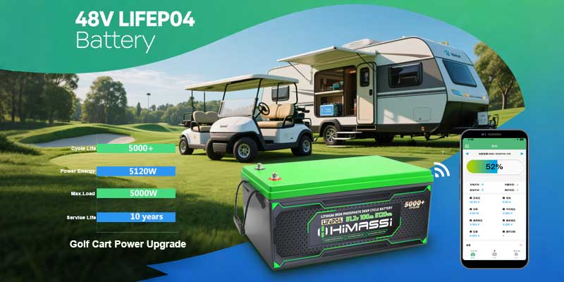
In the world of golf cart battery upgrades and RV energy storage applications, a robust 48V LiFePO4 battery system can be a true game‐changer. Offering longer cycle life, lighter weight, and higher efficiency than traditional lead-acid packs, LiFePO4 (lithium iron phosphate) technology is rapidly becoming the go-to solution for any 48-volt setup. In this in-depth guide, we’ll explore every critical piece—from the heart of your pack (the BMS architecture) to thermal management (temperature sensor layout and heat pipe/heatsink selection) and finally, practical wiring diagrams. By the end, you’ll know exactly how a Himax-customized 48V LiFePO4 battery system can transform your golf cart or RV experience.
1. Overview of a 48V LiFePO4 Battery System
A typical 48V LiFePO4 battery system is built by connecting four 12.8V LiFePO4 modules in series (4S), yielding a nominal voltage of 51.2V. Depending on your capacity needs, you can parallel multiple 4S strings for higher amp-hours. Compared with lead-acid, a LiFePO4 pack delivers:
- Up to 3× longer cycle life(2,000–5,000+ cycles)
- 50%–70% weight reduction, improving vehicle efficiency
- Flat discharge curve, keeping voltage stable until nearly depleted
- Enhanced safety, thanks to the LiFePO4 chemistry’s inherent thermal stability
Whether you’re retrofitting a golf cart battery upgrade or designing an RV energy storage application, mastering the core components of a 48V LiFePO4 battery system is essential for performance and safety.
2. BMS Architecture: The Brain of Your Pack
2.1 Core Functions of a BMS
A high-quality Battery Management System (BMS) ensures your 48V LiFePO4 battery system operates safely and efficiently by:
- Monitoring cell voltagesto prevent over-charge or over-discharge
- Measuring pack currentfor accurate State-of-Charge (SOC) and State-of-Health (SOH) calculations
- Controlling cell-balancingto keep all cells at equal voltage
- Managing temperatureto avoid thermal runaway
- Communicatingdata to external displays or controllers via CAN, SMBus, or UART
2.2 Hardware Modules
A robust BMS architecture typically comprises:
- Analog Front End (AFE)– high-precision ADCs that sample each cell tap
- Microcontroller Unit (MCU)– runs the firmware for protection algorithms and balancing logic
- Power MOSFETs– switch charging/discharging paths on and off under fault conditions
- Communication Interfaces– CAN or SMBus ports for real-time monitoring on a dashboard or smartphone app
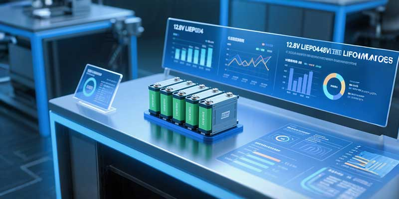
2.3 System Topology Example
For a 15S configuration (e.g., 48V nominal with 15 × 3.2V cells), each of the 16 cell taps connects to the BMS’s AFE channels. A robust layout ensures precise voltage readings and rapid cell balancing when needed. Himax’s BMS architecture can be tailored to suit anything from a 4S golf cart setup to a 16S RV bank.
2.4 Communication & Monitoring
Integrating an external controller—whether your golf cart’s CAN bus or an RV’s energy management system—lets you view live SOC, cell voltages, pack current, and temperature. Himax offers both wired CAN solutions and wireless Bluetooth monitoring modules for on-the-go insights.
3. Battery Temperature Sensor Layout & Installation
3.1 Sensor Types: NTC vs. Thermocouple
- NTC Thermistors(negative temperature coefficient) are cost-effective, easy to integrate, and perfect for pack-level monitoring.
- Thermocouplesprovide faster response and wider temperature ranges—ideal for high-power EV applications.
3.2 Optimal Placement Strategy
To prevent hotspots in your 48V LiFePO4 battery system, place sensors at:
- Intake sideof each module, to measure incoming temperature;
- Center of the module, where heat typically accumulates;
- Exhaust side, to track outgoing temperature.
This three-point layout ensures the BMS can detect uneven heating and trigger cooling or alerts before damage occurs.
3.3 Mounting Techniques
Affix sensors using thermally conductive silicone pads or double-sided thermal tape. Ensure firm contact with cell surfaces, and route sensor wires neatly to the BMS board to maintain signal integrity.
3.4 Data Logging & Alarms
Program your BMS firmware to log temperature trends and flag any reading outside your safe window (e.g., 0–45 °C). Himax can pre-load your target thresholds and integrate buzzer or relay outputs for over-temp alarms.

4. Heat Pipe & Heatsink Selection for Effective Cooling
4.1 Understanding Heat Pipe Options
- Flat heat pipesexcel in low-profile designs like RV under-seat banks.
- Oscillating heat pipesoffer rapid heat transfer in high-power golf cart applications.
4.2 Heatsink Materials & Fins
- Aluminum alloysare lightweight and cost-effective, perfect for passive cooling on your 48V LiFePO4 battery system.
- Copper basesprovide superior conductivity but at higher cost and weight.
Fin geometry—such as pin, straight-fin, or waffle-fin—affects airflow and thermal performance. Himax engineers select the ideal balance of size, weight, and cost for your specific pack.
4.3 Key Selection Criteria
- Thermal resistance (°C/W): lower is better for heat dissipating.
- Package dimensions: must fit within your golf cart’s battery tray or RV compartment.
- Weight budget: lighter solutions boost vehicle range.
4.4 Advanced Hybrid Cooling
For demanding RV energy storage applications, combine heat pipes with Phase Change Materials (PCM) or even liquid cooling loops. Himax can supply turnkey modules that integrate all three for peak performance.
5. Typical Wiring Diagrams & Best Practices
5.1 Cell-Tap Cabling & Labeling
Use high-flex, tinned copper ribbon cables rated for your anticipated current (e.g., 16 AWG for 100 A systems). Clearly label each Cell-Tap harness (B1+, B2+, … B15+, B-) to avoid wiring mistakes.
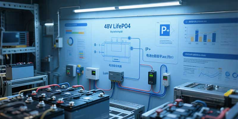
5.2 Main Terminals: B–, P– & P+
- B– (Battery Negative)ties your pack to the BMS ground.
- P– (Pack Negative)feeds into your charger/inverter negative.
- P+ (Pack Positive)connects directly to your load’s positive input.
5.3 Pre-Power Safety Checks
Before energizing, measure each cell tap with a multimeter to confirm proper sequence and no open-circuit. Verify continuity between B–, P–, and P+ to prevent accidental polarity reversals.
5.4 Common Pitfalls & Troubleshooting
- Mis-labeled tapscan lead to over-voltage on a cell—always double-check.
- Loose terminal screwscan introduce resistance and heat—torque to manufacturer spec.
- Routing near hot surfacesmay damage cables—use protective conduit or heat-resistant sleeving.
6. Conclusion & Himax Customization Edge
A well-engineered 48V LiFePO4 battery system combines precise BMS architecture, strategic temperature sensor layout, optimized heat pipe/heatsink selection, and foolproof wiring diagrams for reliable operation in golf cart battery upgrades or RV energy storage applications.
With Himax’s turnkey customization—ranging from bespoke BMS firmware and thermal modules to fully labeled harnesses—you gain peace of mind and best-in-class performance. Ready to elevate your ride or roam? Reach out to our experts for a tailored 48V LiFePO4 solution that fits your exact needs.