By Alden | Battery Engineer — Manufacturing & Quality Control, Himax Electronics
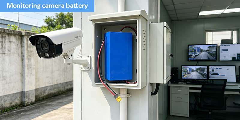
A surveillance camera that loses power at the wrong moment isn’t just an inconvenience — it’s a failure. Choosing the right batteries for security systems is the first step to prevent that. So in this post, I walk through a real battery pack we engineered specifically for 24/7 monitoring devices: what we built, why we made every decision we did, and most importantly, what makes a LiFePO4 battery the right backbone for serious security applications.
The Power Problem No One Talks About
Typically, when security system integrators evaluate their installations, they spend hours choosing lenses, night vision specs, and storage capacity. However, power rarely gets the same attention — until something fails.
The reality is that batteries for security systems carry a disproportionate responsibility. After all, a camera is only as reliable as the energy source behind it. Whether it’s grid outages, brownouts, or solar input fluctuations — the battery is, ultimately, the last line of defense between a live feed and a black screen.
This project started with exactly that concern. A customer building professional monitoring equipment needed a compact, dependable battery pack that could handle continuous discharge loads, survive temperature variation, accept solar charge input, and pass market certification requirements. They came to us at Himax Electronics, and what we built together tells a good story about what serious battery engineering actually looks like. That’s how we design all our batteries for security systems — with no compromise on reliability.
Full Specification Breakdown
Let’s start with the numbers. To be precise, here’s what this battery pack is built around:
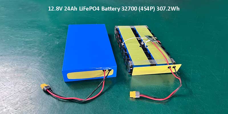
| Parameter | Value |
| Chemistry | LiFePO4 (Lithium Iron Phosphate) |
| Configuration | 4S4P (4 series × 4 parallel) |
| Cell Model | 32700 / 3.2V / 6000mAh per cell |
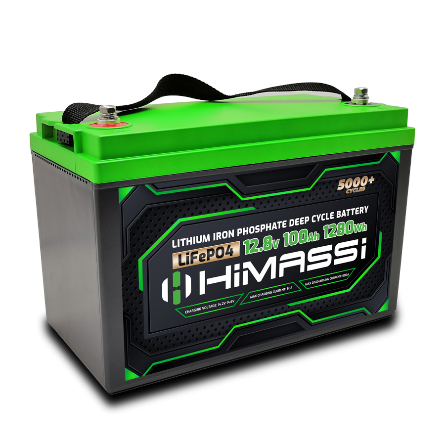
| Nominal Voltage | 12.8V |
| Capacity | 24Ah |
| Energy | ≈ 307.2Wh |
| Max Continuous Discharge | 10A |
| Charge Current | ≤ 1C (solar input compatible) |
| Connector | XT60 Female |
| Wire Length | 200mm |
| Dimensions | 42.5 × 265.0 × 136.0 mm |
| Enclosure | Blue PVC heat shrink |
| Shipping SOC | 50% |
To put it in perspective, 307.2Wh in a package that fits inside a compact monitoring enclosure. That’s the core engineering challenge: squeezing serious energy density into a geometry-constrained form factor without compromising safety or serviceability.
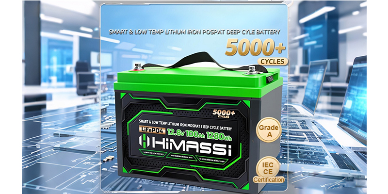
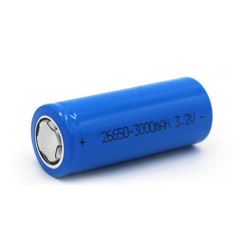
Why 32700 LiFePO4 Cells Are the Ideal Batteries for Security Systems
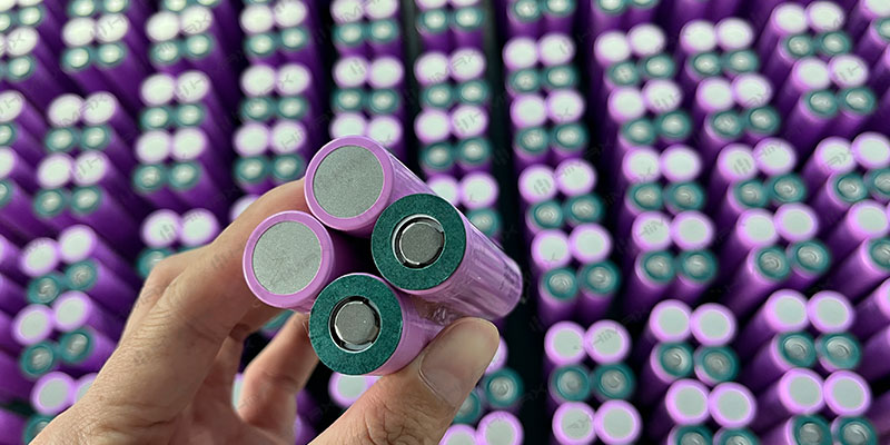
Every battery pack decision starts with the cell. That’s because, for security applications, I consistently reach for LiFePO4 chemistry — and, more specifically, the 32700 form factor when high capacity is needed in a cylindrical format.
For example, the 32700 cell — 32mm diameter, 70mm length — offers one of the best capacity-to-size ratios in the cylindrical cell world. At 3.2V and 6,000mAh per cell, it brings substantial energy into each slot of the battery bracket — consequently, without the heat accumulation concerns you get with denser NMC chemistries.
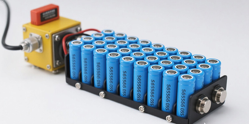
Understanding the 4S4P Configuration
This pack uses 16 cells total, arranged in a 4S4P topology.
Specifically, the “4S” configuration means four cells in series — which multiplies voltage: 4 × 3.2V = 12.8V nominal.
Meanwhile, the 4P arrangement multiplies capacity: 4 × 6,000mAh = 24,000mAh (24Ah).
As a result, it’s an elegant arithmetic that turns sixteen modest cylinders into a powerful, unified energy source.
| Why this matters for security use: Series gives you the voltage headroom to run standard 12V monitoring equipment directly. Parallel gives you the runtime — at a typical 3–5A draw from a surveillance controller, this pack delivers 5–8 hours of backup capacity without breaking a sweat. |
LiFePO4 vs. The Alternatives: An Honest Comparison
When customers ask me what battery chemistry to use for their security system battery, I always walk through the trade-offs honestly.
| Criteria | LiFePO4 | Lead-Acid | NMC Li-ion |
| Cycle Life | 2000+ cycles | 300–500 | 500–1000 |
| Thermal Safety | Excellent | Moderate | Moderate |
| Weight | Light | Heavy | Lightest |
| Voltage Stability | Very flat curve | Drooping | Good |
| Suitable for always-on | Yes | Limited | Yes (with care) |
Unsurprisingly, for an always-on, low-maintenance deployment — which is exactly how most security systems operate — LiFePO4 wins convincingly. In fact, It’s flat discharge curve means the devices it powers see stable voltage throughout the cycle — rather than a gradual sag that can destabilize camera electronics.
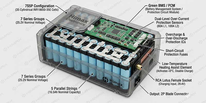
The BMS: Designing for “Set It and Forget It” Reliability
Analogously, a battery without a good BMS is like a security camera without tamper protection. The battery management system is what keeps this pack safe during the years of unattended operation that a typical security installation demands.
Here’s how we configured the BMS for this project:
| Protection Feature | Parameter |
| Overcharge cutoff | 14.6V ± 0.05V |
| Over-discharge cutoff | 10V ± 0.05V |
| Max continuous discharge | 10A |
| Short circuit protection | Yes |
| Overcurrent protection | Yes |
| Cell balancing | Yes (passive balancing) |
| Operating temperature | −10°C ~ +50°C |
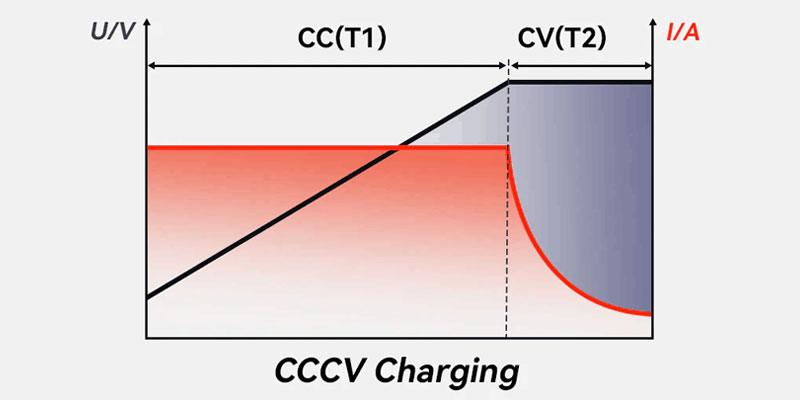
First, to ensure reliable solar charging, the charge parameters were specifically aligned with solar input compatibility. After all, solar chargers can be erratic: clouds pass, panels overheat, charge controllers vary. Therefore, consequently, the BMS had to absorb that variability without ever letting the cells see dangerous voltages. Moreover, the 14.6V ceiling is exactly right for 4S LiFePO4 — it gives enough headroom for full charge without risking cell degradation.
Cell balancing deserves special mention. Over time, even well-matched cells drift apart slightly in capacity. Without balancing, the weakest cell in a series string limits the entire pack — and, as a result, can become over-discharged while the others still hold charge. Critically, the passive balancing circuit in this BMS bleeds off excess energy from stronger cells during charging — keeping the string aligned and significantly extending the useful life of the entire pack.
“A battery that doesn’t fail silently is a battery worth trusting. Every protection layer in this BMS exists so that a technician doesn’t have to visit a camera pole at 3am.”
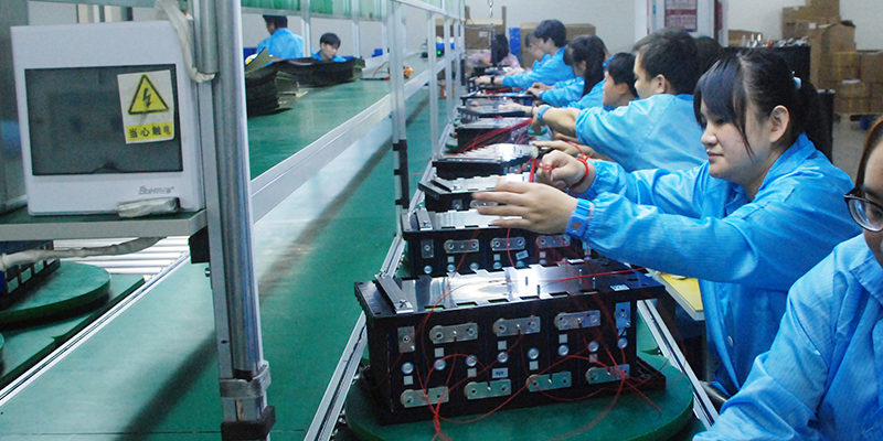
Manufacturing Process: What Happens Before the Blue Wrap Goes On
I oversee production on packs like this personally, and I want to share what actually goes into building a reliable battery — because it’s more rigorous than most people assume.
1. Cell Inspection and Sorting
Before a single cell goes into a bracket, every one is tested for open-circuit voltage and internal resistance. In practice, cells that don’t meet our matching tolerance get pulled. Putting mismatched cells in parallel creates internal circulating currents that degrade the pack over time. This step is non-negotiable.
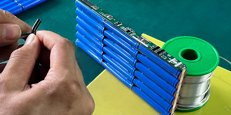
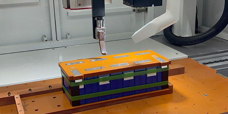
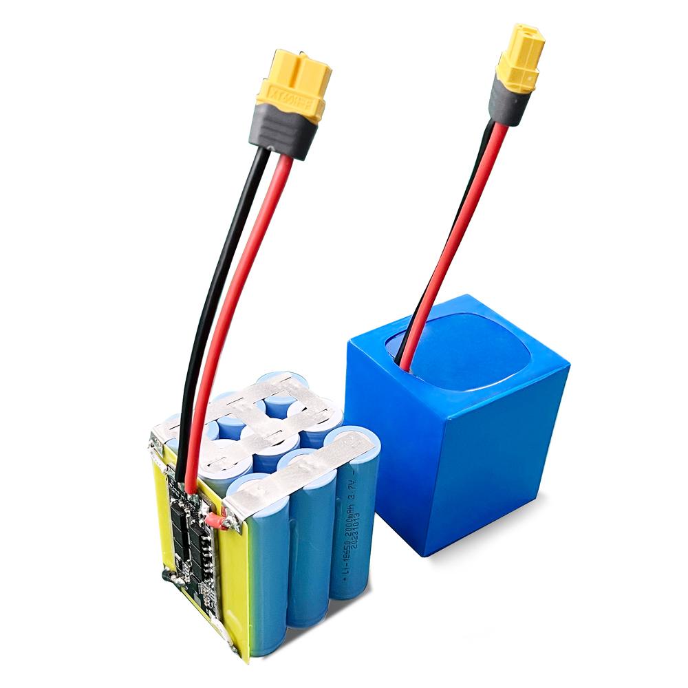
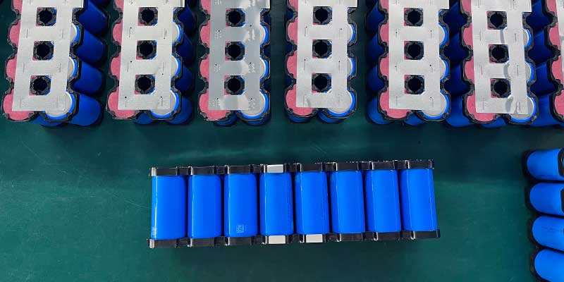
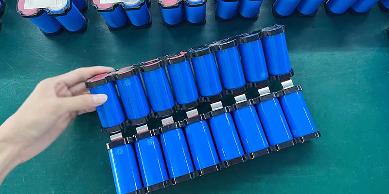
2. Bracket Assembly and Nickel Strip Welding
First, the 16 cells are loaded into a plastic cell holder that both organizes the pack geometry and provides electrical isolation between rows. Nickel strips are spot-welded to connect cells in the correct series-parallel topology. Weld quality is checked for consistency — a bad weld means high contact resistance, heat, and eventual failure.
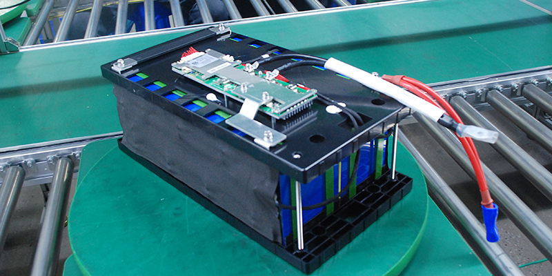
3. BMS Integration
Next, the BMS board is connected to the cell groups via the balance leads and the main power terminals. After wiring, we perform a full functional test: charge the pack, discharge under load, verify all protection thresholds trigger correctly, and confirm the balance circuit is active.
4. Aging Test and Capacity Verification
Then every pack goes through an aging cycle before shipment. We charge to full, rest, then discharge to rated cutoff while logging capacity. Thus, any pack that comes in below 95% of rated capacity doesn’t leave the floor.
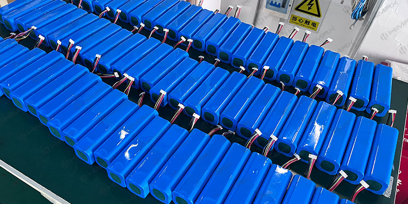
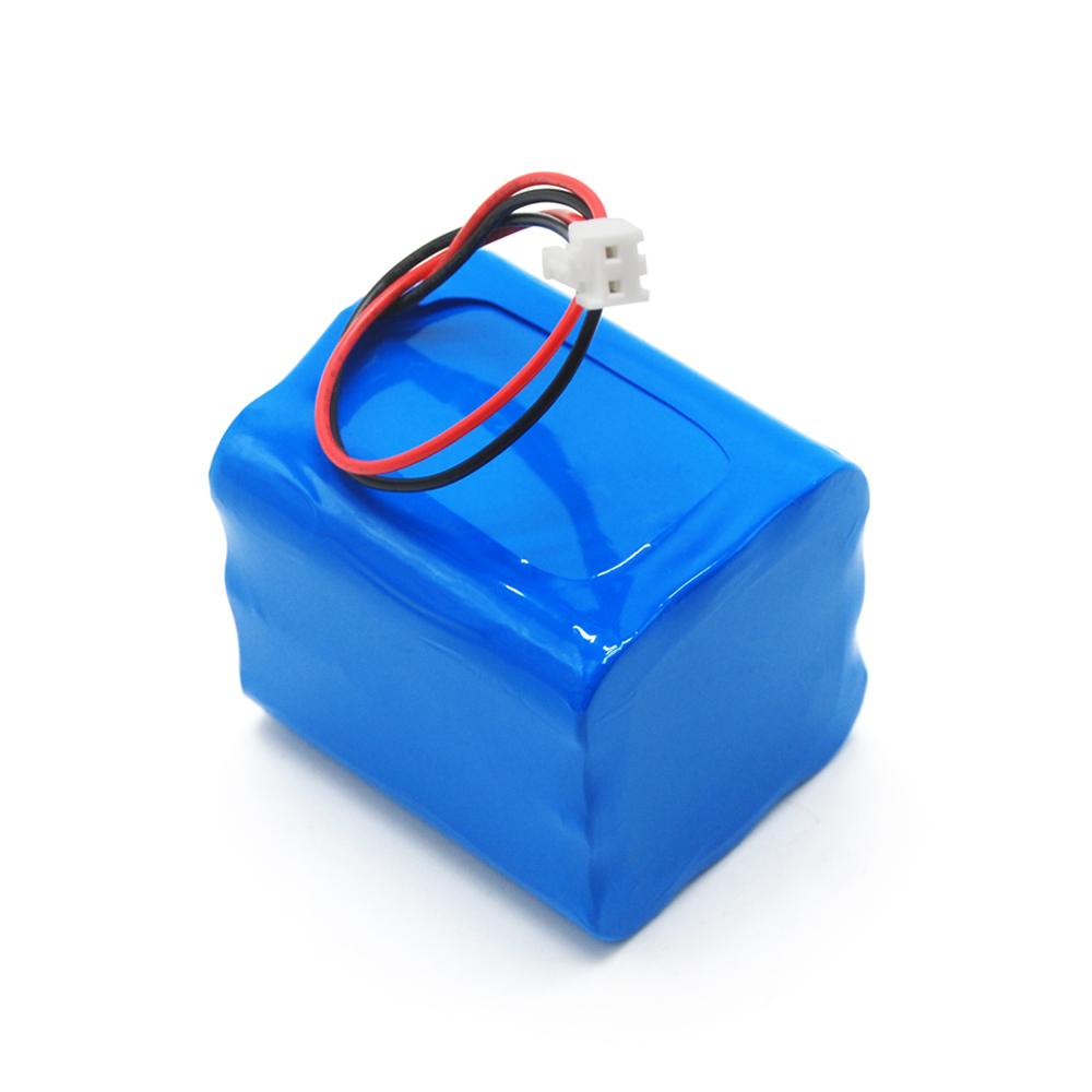
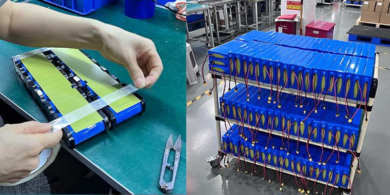
5. Blue PVC Encapsulation and Labeling
The finished cell assembly is wrapped in blue PVC heat shrink, providing electrical insulation, mechanical cohesion, and a clean, professional appearance. Certification labels are then applied according to the customer’s requirements, with production dates coordinated across cell markings and compliance stickers to ensure full traceability.
Beyond Surveillance: LiFePO4 in the Broader IoT Ecosystem
Security cameras don’t operate in isolation. Modern monitoring infrastructure includes smart sensors, access control systems, connected gateways, and remote IoT nodes — all of which share the same power reliability requirements.
Similarly, the same LiFePO4 engineering principles that make this pack ideal for CCTV backup apply across the full spectrum of connected device applications. If you’re working on IoT device power, explore our IoT battery solutions to see how these principles translate across applications.
5 Things to Evaluate When Choosing Batteries for Security Systems
Based on the projects we’ve completed in this space, here’s what I’d tell anyone evaluating a backup battery for CCTV or monitoring systems:
- Voltage stability under load. Drooping voltage affects camera electronics. LiFePO4’s flat discharge curve keeps equipment operating within spec throughout the cycle.
- Cycle life relative to your replacement cost. Lead-acid may look cheaper upfront. But if it needs replacing every 2 years versus every 8–10 years for LiFePO4, total cost of ownership tells a different story.
- BMS protection depth. At minimum: overcharge, over-discharge, overcurrent, short circuit, and temperature protection. Cell balancing extends pack longevity significantly.
- Fourth, mechanical fit for your enclosure. Custom battery packs can be dimensioned to fit existing product housings exactly. In fact, a 1mm mismatch in an injection-molded enclosure can trigger a full factory retool. Therefore, getting this right early in the design process is essential.
- Certification alignment for your target market. Different regions require different marks. Build this into your battery spec from day one — retrofitting certification compliance is expensive and slow.
Final Thoughts: Engineering Trust Into Every Cell
There’s something I find genuinely meaningful about building batteries for security systems. Whether it’s a single camera or a large surveillance network, these batteries must never become the weakest link. In reality, the end user — the person whose property this camera watches over — will never think about the battery. Nor should they have to. Instead, they should simply know the system works.
That invisibility is the goal. After all, a battery that draws no attention is a battery doing its job. And achieving that kind of quiet reliability requires careful cell selection, a well-configured BMS, rigorous manufacturing process, and honest quality control that doesn’t ship a pack we wouldn’t stake our reputation on.
If you’re designing a security product and need a battery that can carry that same commitment, I’d be glad to talk through it.
Ready to Power Your Security System Right?
Whether you need a standard 12.8V 24Ah LiFePO4 pack or a fully custom battery engineered to your exact specification, our team at Himax Electronics is ready to help. In fact, we’ve built thousands of packs for OEM monitoring and surveillance applications — so let’s build yours.
→ Security System Battery Solutions