By Alden, Battery Engineer – Manufacturing & Quality Control · himaxelectronics.com
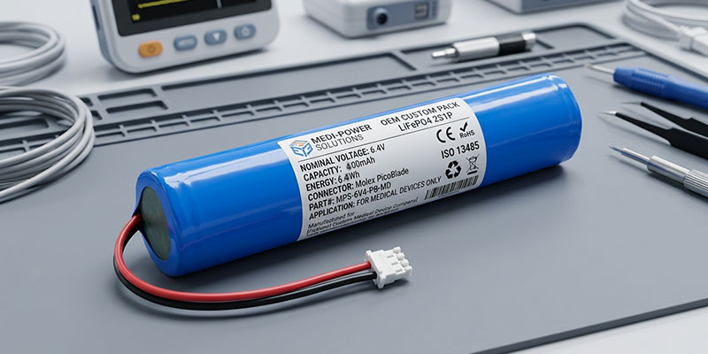
Walk into any modern clinical setting, or look at the wrist of someone managing a chronic condition at home. You will then find portable medical monitoring devices quietly doing critical work. Pulse oximeters tracking blood oxygen saturation. ECG patches recording cardiac rhythms across a 48-hour Holter period. Wearable blood pressure cuffs logging ambulatory readings through a patient’s normal day. What these devices share is not just their clinical purpose. More importantly, they demand a precise, uncompromising battery power that is small in size, reliable in output, and safe under every foreseeable condition.
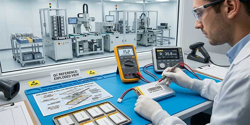
At Himax Electronics, I work in battery pack manufacturing and quality control. From where I stand — at the intersection of electrochemical engineering and production-line reality — the 3.7V 470mAh LiPo battery (model 403438 NTC) is one of the most carefully specified products we build. This article is a technical walkthrough of what this cell is, what it does well, and where it belongs in the design of portable medical monitoring instruments.
Power at the Point of Care: What Medical Monitors Demand from a Battery
Miniaturization vs. Runtime: The Core Engineering Tension
Medical device engineers operate in a space where every cubic millimeter matters. A wearable cardiac monitor cannot be the size of a pager; a handheld pulse oximeter must fit in a nurse’s uniform pocket. Yet these same devices need to run for hours — sometimes continuously for 24 to 72 hours in ambulatory monitoring applications — without recharging. This creates the central tension in portable medical monitoring device battery design: energy density versus physical footprint.
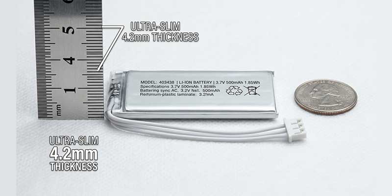
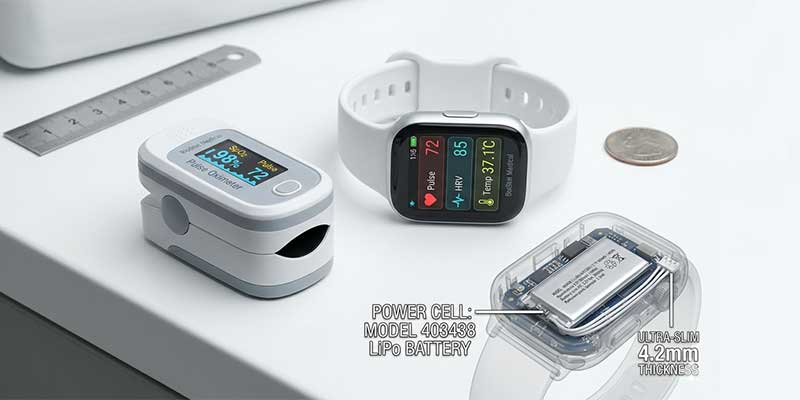
Lithium polymer (LiPo) chemistry resolves this tension more effectively than any alternative. LiPo cells offer gravimetric energy densities in the range of 150–200 Wh/kg. Additionally, they can be manufactured in virtually any planar geometry. As a result, LiPo cells can be shaped to fill the available volume inside an instrument housing, rather than forcing the housing to be designed around a standardized cylindrical cell. The 403438 format — 4.2mm thick, 34.5mm wide, 38.5mm long — is a proven geometry that fits naturally into the slim profile of handheld and wearable medical devices.
Why Lithium Polymer Outperforms Other Chemistries in Medical Applications
NiMH dominated portable medical devices through the 1990s and early 2000s. However, compared to NiMH, lithium polymer offers a higher nominal cell voltage (3.7V vs. 1.2V per cell). Therefore, a single-cell LiPo pack can often replace multi-cell NiMH strings, which reduces pack size, connector complexity, and failure points. The absence of the memory effect, combined with a much flatter discharge curve at low drain rates, ensures that instrument readings do not drift as the battery depletes. For a medical device, this is non-negotiable. For example, consider a blood glucose meter that reports values with 5% accuracy when the battery is full but only 8% accuracy at 30% charge state. Such a device is not a reliable medical device.
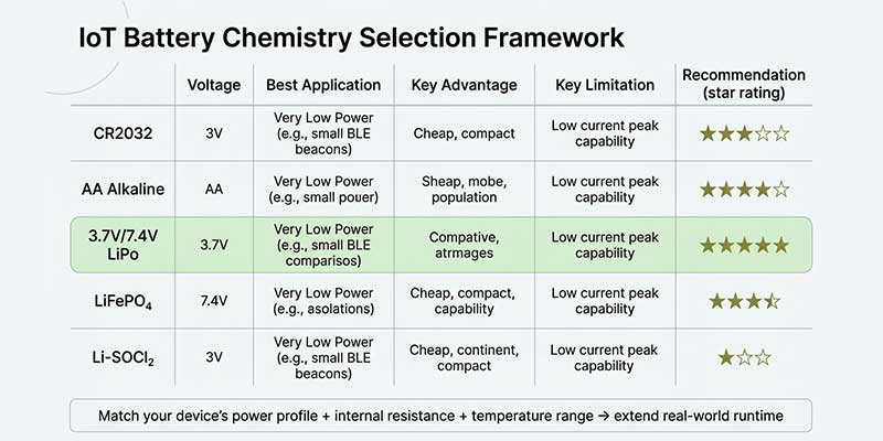
Compared to lithium iron phosphate (LiFePO4), LiPo offers higher energy density at small cell sizes appropriate for handheld instruments. Moreover, its 3.7V nominal voltage aligns naturally with common low-power medical microcontroller and sensor supply rails. Consequently, it often eliminates the need for a boost converter stage.
Product Specifications: 403438 NTC 3.7V 470mAh LiPo Battery Pack
Electrical & Physical Parameters
The Himax 403438 NTC is a 1S1P single-cell lithium polymer pack. Its full specification, drawn from our internal product document HLPGB010A47-1124, is as follows:
| Parameter | Specification | Notes |
| Cell Model | 403438-470 | Lithium-ion Polymer |
| Configuration | 1S1P | Single cell |
| Nominal Capacity | 470mAh | 0.2C to 3.0V cut-off |
| Minimum Capacity | 460mAh | 0.2C to 3.0V cut-off |
| Nominal Voltage | 3.7V | |
| Charge Voltage | 4.2V | CC/CV method |
| Discharge Cut-off | 3.0V | |
| Energy | 1.74Wh | |
| Standard Charge Current | 94mA (0.2C) | Full charge: 6h at 4.2V/94mA |
| Max. Charge Current | 235mA (0.5C) | |
| Max. Continuous Discharge | 470mA (1C) | |
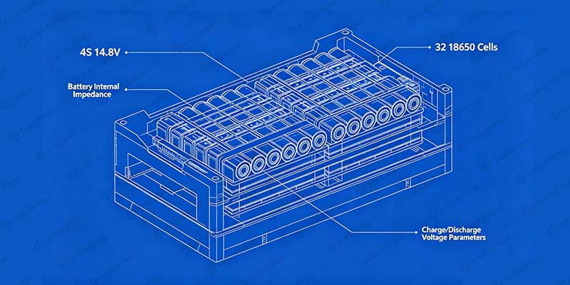
| Internal Impedance | ≤180mΩ (pack) | ≤80mΩ cell only |
| Cycle Life | 300 cycles | ≥80% capacity retained |
| Cell Dimensions | 4.2 × 34.5 × 38.5mm | Max. |
| Pack Dimensions | 4.2 × 34.5 × 41mm | Max., includes PCM |
| Weight | ~11g | Pack with PCM and leads |
| Charge Temp. Range | 10°C to 45°C | |
| Discharge Temp. Range | -20°C to 60°C | |
| Storage Temperature | -10°C to 45°C | |
| Storage Charge State | 30–70% SOC | Ship voltage: 3.8–4.0V |
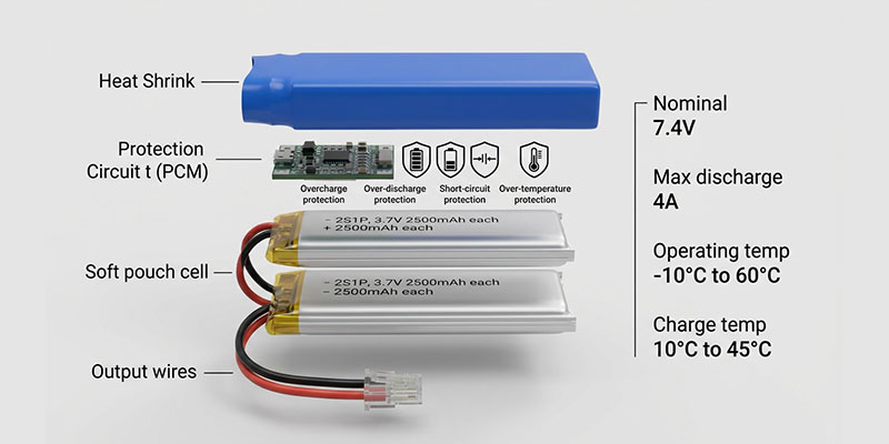
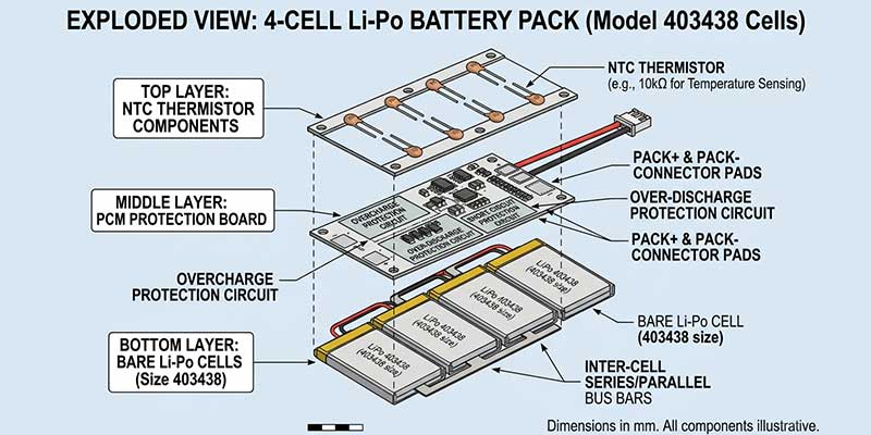
Protection Circuit Module (PCM) & NTC Thermistor
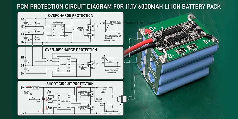
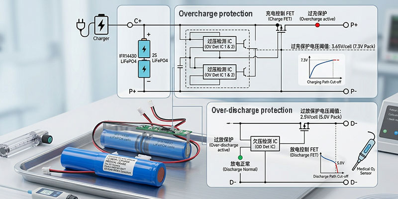
Every 403438 NTC pack shipped from our factory includes a fully integrated Protection Circuit Module. In battery manufacturing, the PCM is not optional for medical applications. In fact, it is the safety layer that prevents the electrochemical cell from ever reaching a condition that could injure a patient or damage equipment. Our PCM for this model is characterized as follows:
- Overcharge detection at 4.28V ±0.02V, reset at 4.08V ±0.05V, max. detect delay 1.3 seconds
- Over-discharge detection at 3.0V ±0.1V, reset at 3.0V ±0.1V, max. delay 166.4ms
- Overcurrent detection at 1–3A, resetting automatically on load removal
- Short-circuit protection triggering on external short, resetting on load removal
- PCM resistance ≤65mΩ, contributing minimally to system impedance
The “NTC” in the model designation refers to the integrated 10kΩ Negative Temperature Coefficient thermistor on the PCM board. This component provides the host instrument’s charging circuit with real-time temperature data, enabling charge suspension if pack temperature rises beyond safe bounds. For medical devices charged frequently in varied ambient conditions, NTC-based thermal monitoring is the standard expectation from device manufacturers. Furthermore, it is increasingly becoming a regulatory requirement in markets that demand IEC 62133 compliance.
Connector & Output Configuration
The standard output uses 1571 26AWG wire at 50±5mm lead length, terminated with an HTA2009H-3P three-pin connector. The three-pin configuration carries positive, negative, and NTC signal lines in a single mating connector. This design simplifies PCB layout in the host instrument. At the same time, it ensures the NTC data line cannot be accidentally disconnected. The compact connector footprint is well-suited to the slim board layouts typical of wearable and handheld medical devices.
Application Scenarios: Where This Battery Powers Medical Innovation
The 403438 NTC 3.7V 470mAh pack was specified for portable medical monitoring applications from the outset. Its planar geometry, 1.74Wh energy density in an 11g package, NTC thermal monitoring, and full PCM protection address the requirements of a broad range of instruments across the point-of-care and home healthcare segments.
Pulse Oximeters & SpO2 Monitoring Devices
Fingertip and handheld pulse oximeters are among the highest-volume portable medical instruments globally, used across hospital wards, ambulances, sports medicine, and home care. A typical continuous-monitoring pulse oximeter draws 30–80mA depending on display type and Bluetooth transmission duty cycle. At 470mAh nominal capacity, the 403438 NTC pack supports 6 to 15 hours of continuous operation — enough for a full clinical shift or an overnight home monitoring session.
The flat LiPo discharge profile ensures the SpO2 sensor’s LED drive current remains consistent throughout the measurement window, preventing the reading drift that can occur when alkaline cell voltage decline affects the analog front-end reference. The 4.2mm pack thickness integrates cleanly into fingertip and clip-style oximeter housings where space is acutely constrained.
Portable ECG & Cardiac Monitors
Single-lead and multi-lead portable ECG monitors span a wide range of power budgets. Entry-level single-lead devices for telemedicine applications typically operate at 20–50mA average, where the 470mAh pack offers 9 to 23 hours of recording time. Holter monitors requiring 24–48 hours of continuous recording may use the 403438 cell as a building block in multi-cell parallel configurations that scale runtime proportionally.
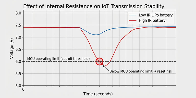
In ECG applications, battery voltage stability directly affects acquired signal quality. A lithium polymer cell’s flat 3.7V discharge plateau means the analog signal chain — particularly the low-noise amplifier and ADC reference — sees a stable supply voltage for the vast majority of the pack’s usable capacity. This is a primary reason ECG device designers specify LiPo over NiMH for new designs.
Wearable Patient Vital Signs Monitors
The fastest-growing segment of portable medical monitoring is wearable devices: patches, wristbands, and adhesive sensors that track multiple physiological parameters continuously over days or weeks. The 403438’s 4.2mm thickness and 11g mass make it one of the lightest and thinnest options in the 400–500mAh class. For wrist-worn or chest-patch devices, these physical properties translate directly into patient comfort and wearability compliance — a clinical outcome factor as important as raw runtime in continuous monitoring scenarios.
Handheld Blood Glucose Meters
Blood glucose meters operate in a burst-power profile: low-current standby punctuated by brief high-current measurement and display events. The 403438 NTC handles this load profile efficiently. The PCM’s overcurrent threshold of 1–3A provides headroom well above the peak demand of a typical glucose meter display and measurement circuit. At 300 cycles to 80% retained capacity, the pack covers approximately three to four years of three-times-daily use — matching realistic instrument lifetimes and reducing patient-facing battery replacement costs.
Ambulatory Blood Pressure Monitors (ABPM)
ABPM devices inflate a cuff automatically at programmed intervals — often every 15 to 30 minutes — across a 24-hour monitoring period. The pump motor draws several hundred milliamps for 2–5 seconds per inflation cycle. The 403438 NTC’s maximum continuous discharge rating of 470mA (1C) accommodates these brief high-current peaks, while the average current across a full 24-hour ABPM session — accounting for low-power standby intervals between inflations — falls within the pack’s optimal efficiency range.
Digital Thermometers & Infrared Forehead Scanners
Non-contact infrared thermometers represent the cost-sensitive, high-volume end of the portable medical monitoring market. In these applications, the battery is often the largest single component by volume, making size optimization directly impactful on product design. The 403438’s planar geometry fits naturally behind the instrument’s display assembly, eliminating the wasted space that cylindrical AA or AAA cells leave in angular housings. The 3.7V output drives the MCU, IR sensor, and display directly without a boost converter in most modern low-power IC designs, simplifying the power management architecture.
The Role of NTC Thermistor Protection in Medical Battery Safety
I want to address NTC protection specifically, because in my experience it is frequently under-specified by device engineers who treat it as optional rather than foundational. For any device charged repeatedly by end users — which describes virtually every reusable portable medical monitor — I consider it non-negotiable.
A lithium polymer cell charged above 45°C experiences accelerated electrolyte decomposition, lithium plating risk at the anode, and — at higher temperatures — the onset of exothermic reactions that can lead to thermal runaway. In a clinical environment, a bedside charger may sit near a heat vent; at home, a patient may charge their device in direct sunlight. Without a temperature signal from the battery, the host charger has no way to detect these conditions and suspend charging before damage occurs.
The 10kΩ NTC thermistor in the 403438 pack provides a resistance signal that scales predictably with temperature, enabling temperature-gated charge inhibit in the charger’s control IC. This costs almost nothing to implement in firmware, but provides the difference between a safe product and a liability. For medical device manufacturers targeting IEC 62133 compliance or preparing regulatory submissions, NTC-equipped battery packs simplify the safety case documentation considerably.
Safety Testing & Compliance Standards
IEC 62133 & Medical Device Battery Compliance
The Himax 403438 NTC is characterized against GB/T 18287-2013, UL 1642, and CE 612400 standards, establishing the baseline for cell-level safety evaluation. For OEM customers targeting medical device regulatory approvals — FDA 510(k) submissions, CE marking under EU MDR 2017/745, or other national filings — the battery pack’s safety test documentation forms part of the device technical file. Key standards we align with include IEC 62133-2 (safety requirements for portable sealed secondary lithium cells and batteries) and IEC 62368-1. Customers requiring additional country-specific certifications can request third-party laboratory coordination through Himax’s OEM support process.
Mechanical & Abuse Testing Results
The 403438 cell and pack undergo the following standard mechanical and safety abuse tests as part of our product characterization program:
- Crush test: no fire, no explosion at 13kN applied force via 32mm piston to 17.2MPa
- Drop test: no explosion, no fire, no smoke after two 1-meter drops onto concrete per axis of symmetry
- Vibration test: no leakage, no fire, no explosion after 30 minutes per axis (XYZ) at 1.6mm amplitude, 10–55Hz swept at 1Hz/minute
- Overcharge safety: no explosion, no fire at 3× max charge current, 4.2V CV for 7 hours
- Over-discharge safety: no explosion, no fire after 1C discharge for 2.5 hours
- Short-circuit safety: surface temperature below 150°C; no explosion, no fire
- Thermal stability: no explosion, no fire after ramp to 130°C at 5°C/min, held 30 minutes
Full test records are available in product specification document HLPGB010A47-1124 (Rev. A0) and provided as part of the technical package for OEM customers conducting device-level risk assessments under ISO 14971.
OEM Customization for Medical Device Manufacturers
The standard 403438 NTC configuration covers a broad range of portable medical monitoring applications. Where design constraints require departures from standard, Himax’s OEM manufacturing capability supports the following customizations:
- Alternate lead length: 30mm to 150mm, depending on internal routing requirements
- Alternate connector types: JST PH, Molex PicoBlade, board-to-wire crimp terminals, or bare wire pad termination for direct PCB soldering
- Foam or adhesive backing for direct-mount wearable device assemblies
- Custom PCM configurations with alternate overcharge, over-discharge, and overcurrent thresholds
- NTC resistance value variants (4.7kΩ, 22kΩ) for compatibility with different charger IC reference designs
- Pack labeling including customer part numbers, barcode labels, and QR codes for device traceability programs
- AQL 0.65 incoming inspection as standard; tightened inspection plans available for high-reliability medical programs
All OEM programs begin with a sample evaluation phase. We recommend that device engineers validate battery integration in the full instrument assembly — including thermal validation under worst-case charge conditions — before committing to production volume. Typical production lead times are 4–6 weeks for standard configurations, with batch-specific test records provided at every shipment for lot traceability.
Interested in integrating the 403438 NTC 3.7V 470mAh LiPo battery into your portable medical monitoring device? Contact Himax Electronics for sample units, custom configuration discussions, or OEM technical documentation. Our team supports customers from initial specification through regulatory submission — with full lot traceability and quality documentation at every stage.
Conclusion
The 403438 NTC 3.7V 470mAh lithium polymer battery pack is a purpose-built solution for the power challenges of portable medical monitoring devices. Its planar geometry fits the physical constraints of handheld and wearable instruments. Its flat discharge curve and stable 3.7V output protect the integrity of medical measurements from full charge to near-end of discharge. The integrated NTC thermistor and full PCM protection address the safety requirements that medical device regulatory frameworks demand.
Across pulse oximeters, ECG monitors, blood glucose meters, ambulatory blood pressure devices, and wearable vital signs sensors, the 403438 NTC delivers consistent, measurable performance backed by a manufacturing and quality control process grounded in real production data — not just specification-sheet claims.
Written by Alden, Battery Engineer – Manufacturing & Quality Control, Himax Electronics.